Privilege, Exceptions, and System Instructions
September 8, 202630 min readintermediate
An application should not be able to reprogram the interrupt controller, overwrite another process’s memory, or halt the processor. These are operations reserved for the operating system kernel. The hardware…
An application should not be able to reprogram the interrupt controller, overwrite another process’s memory, or halt the processor. These are operations reserved for the operating system kernel. The hardware mechanism that enforces this boundary is the privilege level: a mode bit (or a small set of mode bits) baked into the processor state that determines which instructions and resources the currently running code may access. When an application needs a service that only the kernel can provide (reading a file, allocating memory, sending a network packet), it issues a system call, which is a controlled transfer of execution from user privilege to kernel privilege through a well-defined entry point.
This chapter describes how the three major ISA families (RISC-V, AArch64, and x86-64) define privilege levels, how exceptions and interrupts transfer control between levels, how the system-call mechanism works, and how the same privilege architecture supports hardware virtualization. The goal is a concrete understanding of the mechanisms, not a catalog of every control register. The ISA manuals [1][2][3][4] are the authoritative references for the full details.
01.The Need for Privilege Separation
Without privilege separation, any program could execute any instruction. A buggy application could disable interrupts and freeze the system. A malicious program could read the kernel’s page tables, extract cryptographic keys from memory, or overwrite the interrupt vector table to redirect all exceptions to its own code.
Privilege separation solves these problems by partitioning the instruction set and the processor’s control registers into categories. Unprivileged instructions (arithmetic, loads, stores to user-accessible memory, branches) are available at every privilege level. Privileged instructions (interrupt control, page-table management, cache maintenance, halt) are available only at the highest levels. An attempt to execute a privileged instruction at an insufficient privilege level raises an exception, and the operating system can terminate the offending process.
02.RISC-V Privilege Modes
The RISC-V privilege architecture [1] defines three privilege modes:
The three modes correspond roughly to the three layers of a Unix-like system: firmware (M-mode), kernel (S-mode), and user applications (U-mode). A hypervisor extension (the H-extension) adds two further modes, VS-mode (virtual supervisor) and VU-mode (virtual user), for running guest operating systems under a hypervisor in HS-mode.
RISC-V CSRs
Each privilege level has its own set of control and status registers (CSRs). The naming convention prefixes the CSR name with the mode letter: mstatus for machine status and sstatus for supervisor status. Key CSRs include:
Table 1. Selected RISC-V CSRs by privilege level
| CSR | Level | Purpose |
|---|---|---|
| mstatus | M | Global interrupt enable, privilege stack |
| mtvec | M | Machine trap vector base address |
| mepc | M | Machine exception program counter |
| mcause | M | Cause of the last machine trap |
| medeleg | M | Delegate exceptions to S-mode |
| mideleg | M | Delegate interrupts to S-mode |
| sstatus | S | Supervisor interrupt enable |
| stvec | S | Supervisor trap vector base address |
| sepc | S | Supervisor exception program counter |
| scause | S | Cause of the last supervisor trap |
| satp | S | Supervisor address translation and protection |
CSRs are accessed through three atomic read-modify-write instructions: CSRRW (read and write), CSRRS (read and set bits), and CSRRC (read and clear bits). Each has an immediate-operand variant (CSRRWI, CSRRSI, CSRRCI).
Exception delegation
RISC-V allows M-mode firmware to delegate specific exceptions and interrupts to S-mode through the medeleg and mideleg CSRs. When a delegated exception occurs in S-mode or U-mode, the trap goes directly to the S-mode handler without passing through M-mode first. This reduces the overhead of system calls and page faults, which are the most frequent exceptions in a typical operating system.
03.ARM Exception Levels
AArch64 defines four exception levels (ELs) [2]:
The levels are numerically ordered: higher numbers mean higher privilege. An exception always goes to an equal or higher level, never to a lower one. An exception return (ERET) drops to an equal or lower level.
The four-level scheme gives ARM a built-in virtualization layer (EL2) and a secure-world layer (EL3) that other ISAs must approximate with software. TrustZone uses EL3 to partition the system into a “Normal World” (EL0/EL1/EL2) and a “Secure World” (Secure EL0/EL1) with hardware-enforced isolation between the two.
AArch64 system registers
AArch64 uses system registers instead of CSRs or MSRs. System registers are accessed through the MRS (Move from System Register) and MSR (Move to System Register) instructions. Each system register is named by a tuple of fields (op0, op1, CRn, CRm, op2), but the assembly syntax uses human- readable names.
Key system registers include SCTLR_EL1 (system control: caching, alignment, endianness), TCR_EL1 (translation control: page size, address width), TTBR0_EL1 and TTBR1_EL1 (translation table base registers for the two halves of the virtual address space), ESR_EL1 (exception syndrome: cause and details of the last exception), and VBAR_EL1 (vector base address register: base of the exception vector table).
Exception vector table
The AArch64 exception vector table is a block of code at an address given by VBAR_ELn, aligned to 2 KB. The table has 16 entries of 128 bytes each, organized by four exception types (synchronous, IRQ, FIQ, SError) and four source contexts (current EL with SP_EL0, current EL with SP_ELx, lower EL running AArch64, lower EL running AArch32). Each entry is large enough for a small dispatch sequence that saves registers and branches to the full handler.
04.x86-64 Privilege Rings
The x86 architecture defines four privilege rings numbered 0 through 3, with Ring 0 being the most privileged and Ring 3 the least [3]:
The current privilege level (CPL) is stored in the low two bits of the CS (code segment) register. A transition from Ring 3 to Ring 0 occurs through a controlled entry point: the SYSCALL instruction (fast system call) or an interrupt gate in the Interrupt Descriptor Table (IDT).
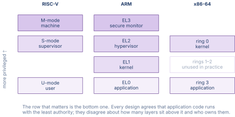
Figure 1 lines the three models up by authority.
x86-64 MSRs
Model-Specific Registers (MSRs) are accessed through the RDMSR and WRMSR instructions, both of which are Ring 0-only. The MSR index is placed in ECX, and the 64-bit value is read from or written to EDX:EAX. Key MSRs include:
Table 2. Selected x86-64 MSRs
| MSR | Purpose |
|---|---|
| IA32_EFER | Extended Feature Enable (long mode enable) |
| IA32_STAR | SYSCALL target CS/SS and return CS/SS |
| IA32_LSTAR | SYSCALL entry point (RIP for Ring 0 handler) |
| IA32_FMASK | RFLAGS mask applied on SYSCALL entry |
| IA32_APIC_BASE | Local APIC base address |
| IA32_PERF_GLOBAL_CTRL | Performance-counter enable |
| IA32_TSC | Timestamp counter |
The MSR space is large and vendor-specific. Intel and AMD share a common set of “architectural” MSRs, but each vendor defines hundreds of additional MSRs for power management, thermal control, performance monitoring, and microcode updates.
The Interrupt Descriptor Table (IDT)
The x86-64 IDT is a table of 256 entries, each pointing to an exception or interrupt handler. The base address and limit of the IDT are stored in the IDTR register, loaded by the LIDT instruction (Ring 0 only). Each entry is a 16-byte gate descriptor that specifies the handler’s code-segment selector, the handler’s offset (the 64-bit entry address), the interrupt stack table (IST) index (for stack switching), and the descriptor privilege level (DPL) that controls which rings may invoke the gate through a software interrupt.
The first 32 entries (vectors 0–31) are reserved for processor exceptions: divide error (0), debug (1), NMI (2), breakpoint (3), overflow (4), bound range exceeded (5), invalid opcode (6), device not available (7), double fault (8), page fault (14), general protection fault (13), and others. Vectors 32–255 are available for external interrupts, typically assigned by the APIC (Advanced Programmable Interrupt Controller).
05.Exception Classification
All three ISAs classify exceptions into categories that determine how the processor responds.
Synchronous vs. asynchronous
A synchronous exception is caused by the currently executing instruction. Examples include illegal-instruction faults, page faults, and system-call traps. The exception is reproducible: re-executing the same instruction in the same state produces the same exception.
An asynchronous exception is caused by an event external to the instruction stream. Interrupts from I/O devices, timer interrupts, and inter-processor interrupts are all asynchronous. They can arrive between any two instructions and are not tied to any specific instruction.
Faults, traps, aborts, and interrupts
The x86 architecture manual [3] defines the following categories of exceptions:
A fault is a synchronous exception where the saved program counter points to the faulting instruction. The handler can fix the condition (for example, by loading a page from disk in response to a page fault) and return to re-execute the faulting instruction.
A trap is a synchronous exception where the saved program counter points to the instruction after the trapping instruction. The system-call instruction is the canonical example. The handler does not re-execute the trapping instruction. It resumes at the next one.
An abort signals a severe error from which execution cannot cleanly resume, either a hardware failure or an inconsistent processor state. The double-fault exception (vector 8 on x86) is the standard example: it fires when a second exception occurs while the processor is trying to deliver a first exception.
An interrupt is an asynchronous exception from an external source. The saved program counter points to the next instruction that would have executed, and the handler returns to that instruction after servicing the device.
RISC-V and AArch64 use similar classifications. RISC-V groups all exceptions under the mcause/scause register, with the high bit distinguishing interrupts (1) from other exceptions (0). AArch64 uses the Exception Syndrome Register (ESR_ELn) to encode the exception class and instruction- specific syndrome data.
06.The System-Call Mechanism
A system call transfers execution from user mode to kernel mode along a controlled path. Each ISA provides a dedicated instruction for this purpose.
RISC-V: ECALL
The ECALL instruction causes a synchronous exception. The trap handler in M-mode or S-mode examines the mcause/scause register to identify it as an environment call, reads the system-call number from register a7 and the arguments from a0–a5, executes the requested service, places the return value in a0, and returns to user mode with MRET or SRET.
RISC-V system call to write a string. a7 holds the syscall number, a0–a2 hold the arguments.
| li a7, 64 # syscall number for write | |
| li a0, 1 # file descriptor (stdout) | |
| la a1, message # buffer address | |
| li a2, 13 # buffer length | |
| ecall # trap to S-mode |
AArch64: SVC
The SVC (Supervisor Call) instruction causes a synchronous exception to EL1. The 16-bit immediate encoded in the instruction is available to the handler via the ESR syndrome field, but Linux ignores it and reads the system-call number from X8 instead. Arguments are in X0–X5, and the return value comes back in X0.
AArch64 system call to write a string. X8 holds the syscall number, X0–X2 hold the arguments.
| MOV X8, #64 // syscall number for write | |
| MOV X0, #1 // file descriptor (stdout) | |
| LDR X1, =message // buffer address | |
| MOV X2, #13 // buffer length | |
| SVC #0 // trap to EL1 |
x86-64: SYSCALL
The SYSCALL instruction is a fast system- call entry that does not go through the IDT. On execution, the processor saves the return address in RCX, saves RFLAGS in R11, masks RFLAGS with the value in the IA32_FMASK MSR, loads RIP from the IA32_LSTAR MSR, and loads the CS and SS selectors from the IA32_STAR MSR. No stack switch happens automatically: the kernel entry code must load the kernel stack pointer from a per-CPU data structure (typically via the GS segment base and the SWAPGS instruction).
x86-64 system call to write a string (Linux convention). RAX holds the syscall number, RDI/RSI/RDX hold the arguments.
| mov rax, 1 ; syscall number for write | |
| mov rdi, 1 ; file descriptor (stdout) | |
| lea rsi, [rip + msg] ; buffer address | |
| mov rdx, 13 ; buffer length | |
| syscall ; fast transition to Ring 0 |
The SYSRET instruction reverses the process: it loads RIP from RCX, restores RFLAGS from R11, and returns to Ring 3.
07.Exception Vectoring
When an exception occurs, the processor must find the correct handler. The mechanism differs across ISAs but follows a common pattern: a base address register points to a table of handler entry points, and the exception cause selects an entry in the table.
RISC-V: mtvec and stvec
The mtvec CSR holds the base address of the machine-mode trap vector. It supports two modes selected by the low two bits. In “direct” mode (low bits = 00), all exceptions jump to the same address (the base). In “vectored” mode (low bits = 01), asynchronous interrupts jump to base + 4 cause_number, while synchronous exceptions still jump to the base address. The handler at the base address inspects mcause to dispatch synchronous exceptions.
The supervisor-level stvec CSR follows the same scheme.
AArch64: VBAR_ELn
The VBAR_EL1 register points to the exception vector table for EL1. The table is 2048 bytes (16 entries of 128 bytes each). The processor computes the handler address as VBAR_EL1 + offset, where the offset depends on the exception type (synchronous, IRQ, FIQ, SError) and the source context. Each 128-byte entry is large enough for a short handler or, more commonly, a register-save sequence followed by a branch to the full handler.
Each exception level has its own VBAR register (VBAR_EL1, VBAR_EL2, VBAR_EL3), so the kernel, hypervisor, and secure monitor each install their own vector tables.
x86-64: IDT and IDTR
The IDTR register holds the base address and limit of the IDT. The processor indexes the IDT by the vector number (0–255) and reads the gate descriptor, which contains the handler’s code-segment selector and 64-bit offset. The processor then switches to Ring 0 (if not already there), optionally switches to a new stack via the Interrupt Stack Table (IST), pushes the old SS, RSP, RFLAGS, CS, and RIP onto the new stack, and jumps to the handler.
08.Privilege Comparison Across ISAs
Table 3. Privilege architecture comparison across three ISAs
| Feature | RISC-V | AArch64 | x86-64 |
|---|---|---|---|
| Privilege levels | M, S, U (+H ext) | EL0–EL3 | Ring 0–3 |
| Levels used in practice | 3 (M, S, U) | 3–4 | 2 (Ring 0, 3) |
| Config registers | CSRs | System regs | MSRs + CRs |
| Config access | CSRRW/S/C | MRS/MSR | RDMSR/WRMSR |
| Syscall instruction | ECALL | SVC | SYSCALL |
| Syscall return | SRET/MRET | ERET | SYSRET |
| Vector base register | mtvec/stvec | VBAR_ELn | IDTR |
| Vector table entries | 1 or per-cause | 16 (per type+source) | 256 |
| HW virtualization | H-extension | EL2 | VMX (VT-x) |
| Secure world | PMP (physical) | TrustZone (EL3) | SGX (enclave) |
The table shows that the three ISAs solve the same problems with different vocabulary and different granularity. RISC-V and AArch64 use clean, orthogonal privilege hierarchies. x86-64 defined four rings but uses only two in practice, with virtualization and security added through separate extensions (VT-x and SGX) rather than through the ring hierarchy itself.
The three stacks side by side
The three architectures agree on what privilege is for and disagree on how many levels it takes to provide it. Drawing them against a common axis makes the correspondence visible, and makes clear where the correspondence breaks down. Figure 2 lines them up with the least privileged level at the bottom.
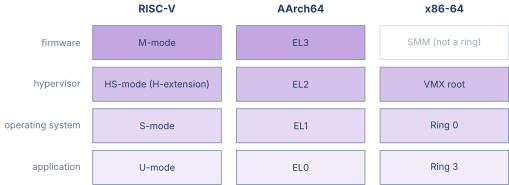
Two mismatches in that figure are worth stating outright. Rings 1 and 2 exist on x86-64 in the architecture and are unused by every mainstream operating system, so the ring numbers do not measure what their spacing suggests. And VMX root is not a ring at all: a hypervisor in VMX root mode still runs at Ring 0, and the extra privilege comes from the mode rather than from the ring number. This is the structural difference between an architecture that planned for virtualization and one that added it later.
09.Hardware Virtualization
A hypervisor runs multiple guest operating systems on a single physical machine. Each guest believes it is running at the highest kernel privilege level, but the hypervisor must intercept any operation that would affect the shared physical hardware. The trap-and-emulate model achieves this by running the guest at a lower privilege level and letting the hardware trap on every privileged instruction the guest executes.
The classic trap-and-emulate requirement
For trap-and-emulate to work cleanly, every privileged instruction must either trap when executed at a lower privilege level or behave safely (producing a harmless result). An instruction that silently does something different at a lower privilege level, without trapping, is called a “sensitive but not privileged” instruction, and its existence breaks clean trap-and-emulate.
x86 and VMX
The original x86 architecture had several sensitive-but-not- privileged instructions (for example, POPF silently ignores the IF bit when executed in Ring 3 instead of trapping). Intel addressed this with VT-x (Virtual Machine Extensions, also called VMX), which adds a new operating mode with two states: VMX root (the hypervisor) and VMX non-root (the guest). In VMX non-root mode, sensitive instructions cause a VM exit: the processor saves the guest’s state to a Virtual Machine Control Structure (VMCS), transitions to VMX root mode, and jumps to the hypervisor’s exit handler. The hypervisor emulates the instruction, updates the guest’s VMCS state, and executes a VMRESUME to return to the guest.
The VMCS is a hardware-managed data structure that holds the guest’s register state, control fields, and exit reason. The hypervisor reads and writes VMCS fields through VMREAD and VMWRITE instructions.
AArch64 and EL2
AArch64’s EL2 is designed for virtualization from the start. The hypervisor runs at EL2, and guest kernels run at EL1. Privileged instructions executed by a guest at EL1 that require hypervisor intervention are routed to EL2 through the exception mechanism. The Hyp Configuration Register (HCR_EL2) controls which operations trap to EL2, giving the hypervisor fine-grained control over the trap set.
Stage-2 translation (the second level of address translation, controlled by EL2) gives each guest its own Intermediate Physical Address (IPA) space, mapped to physical addresses by the hypervisor’s page tables. This eliminates the need for shadow page tables, which are a major source of overhead in x86 virtualization without Extended Page Tables (EPT).
Why two stages of translation
The single largest cost in early x86 virtualization was not instruction emulation but address translation. A guest operating system builds page tables mapping its virtual addresses to what it believes are physical addresses. Those addresses are not physical, because the hypervisor has given the guest only a slice of the machine. Without hardware help the hypervisor must maintain a shadow page table for each guest address space, keep it consistent with the guest’s own tables, and trap every guest write to a page table entry to do so.
Two-stage translation moves the problem into the memory management unit. The guest’s page tables perform stage one, translating a guest virtual address to an intermediate physical address. The hypervisor’s tables perform stage two, translating that intermediate address to a real physical address. Neither party sees the other’s tables and neither needs to trap on the other’s updates. Figure 3 shows the path.
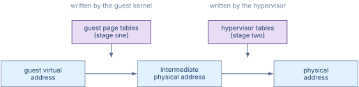
The cost moves rather than disappearing. A translation that misses in the TLB now walks two sets of tables instead of one, and because each level of the stage-one walk itself produces an intermediate address that stage two must translate, a four-level walk on each side costs up to twenty-four memory references rather than four. Hardware answers this with TLB entries tagged by virtual machine identifier, so that a switch between guests does not flush the translations, and with page walk caches that hold the upper levels. The trade is a worse worst case in exchange for removing the shadow-table maintenance entirely.
RISC-V and the H-extension
The RISC-V H-extension adds VS-mode (virtual supervisor) and VU-mode (virtual user) below HS-mode (hypervisor supervisor). When a guest kernel in VS-mode executes a privileged instruction, the trap goes to HS-mode, where the hypervisor emulates it. The extension adds CSRs for two-stage address translation (analogous to ARM’s Stage-2 translation) and for controlling which guest operations trap to the hypervisor.
The H-extension was ratified in 2021 and is supported by recent RISC-V cores (such as the RISC-V implementations in the SiFive Performance series). Its design drew heavily on the lessons learned from both VT-x and AArch64 EL2.
What a VM exit costs
A VM exit is not a branch. It is a full architectural state transition, and understanding what the hardware has to do explains why hypervisor design is dominated by the goal of not causing one. Figure 4 lays out the round trip.

The fixed cost has two parts and only one of them appears in a cycle count. The architectural part is the state save and restore, which on published measurements of early VT-x implementations ran to well over a thousand cycles and has since fallen substantially. The microarchitectural part is that a mode switch of this size disturbs branch predictors, translation caches and the data caches themselves, so the guest resumes into a machine that has partly forgotten what it was doing. That second cost does not show up at the exit instruction and is often the larger of the two.
Every later virtualization feature is an attempt to remove an exit rather than to make one faster. Two-stage translation removes the exits that page table maintenance used to cause. Posted interrupts remove the exit that delivering an interrupt to a guest used to cause. Virtualized local interrupt controllers remove the exits that guest interrupt acknowledgement caused.
10.CSRs, MSRs, and System Registers Compared
The three ISAs use different names and different access mechanisms for configuration registers, but the functional categories are the same.
RISC-V CSRs are a flat 12-bit address space (up to 4096 registers). The top four bits of the address encode accessibility. Bits 11 and 10 indicate whether the register is read/write or read-only, and bits 9 and 8 encode the lowest privilege level that may access it. Access is through the six CSR instructions. The design is simple and uniform.
AArch64 system registers are addressed by a 5-tuple of fields embedded in the MRS/MSR instruction encoding. The encoding space is much larger than 4096, and the system-register namespace is hierarchically organized by function. The encoding is more complex than RISC-V CSRs but provides self-documenting structure.
x86-64 MSRs are addressed by a 32-bit index in ECX. The MSR space is large and sparsely populated, with Intel and AMD defining overlapping but not identical subsets. In addition to MSRs, x86-64 has dedicated control registers (CR0–CR4, CR8) accessed through MOV CRn instructions, and debug registers (DR0–DR7) accessed through MOV DRn instructions. The multiplicity of access mechanisms is a historical artifact: control registers date from the 80386, debug registers from the 80386, and MSRs from the Pentium.
11.Worked Examples
12.Exercises
References
- [1]Waterman, Andrew and Asanovi\'c (2024). “The RISC-V.”
- [2](2024). “ARM.”
- [3](2024). “Intel.”
- [4](2024). “AMD64.”