x86-64: Intel and AMD's Shared Legacy
September 13, 202631 min readintermediate
Consider the task of adding two 64-bit integers stored in registers. On RISC-V, the instruction is a single 32-bit word: add a0, a1, a2. On AArch64, it is likewise a fixed 32-bit encoding: ADD X0, X1, X2. On…
Consider the task of adding two 64-bit integers stored in registers. On RISC-V, the instruction is a single 32-bit word: add a0, a1, a2. On AArch64, it is likewise a fixed 32-bit encoding: ADD X0, X1, X2. On x86-64, the same operation is add rax, rbx, encoded in three bytes: a REX prefix (48), an opcode (01), and a ModR/M byte (D8). Why three bytes instead of four, and why does the instruction format vary in length at all? The answer reaches back to 1978, when Intel shipped the 8086 with a variable-length encoding designed to keep programs small in an era when memory cost roughly one dollar per kilobyte.
That encoding decision, and the commitment to run every program ever compiled for the 8086 without recompilation, is the defining characteristic of the x86 architecture. This chapter traces the evolution from the 8086’s 16-bit real mode through the 80386’s 32-bit protected mode to AMD’s 64-bit long mode, examines the register file and the variable-length instruction encoding in detail, and surveys the SIMD extensions (SSE, AVX, AVX-512) that have turned x86-64 into a credible vector machine. Along the way, it explains the micro-op translation layer that lets modern processors execute a CISC instruction set through a RISC-like out-of-order pipeline.
01.A Short History of x86 Modes
The x86 architecture has passed through three major operating modes, each defined by the width of its address space and its default operand size. Understanding these modes is not merely historical: every x86-64 processor starts in real mode at power-on, transitions through protected mode, and reaches long mode only after the operating system enables it.
Real mode and the 8086 memory model
The 8086, released in 1978, had a 16-bit data bus and a 20-bit address bus. It formed physical addresses by shifting a 16-bit segment register left by four bits and adding a 16-bit offset. The resulting 20-bit address could reach 1 MB of memory. The segment-plus-offset scheme meant that a single logical address could be expressed through multiple segment:offset pairs, and that no hardware protection existed between segments. A program could read or write any byte in the 1 MB space.
Protected mode and the 80386
The 80286 (1982) introduced protected mode with segment-based protection and a 24-bit address bus, but it was the 80386 (1985) that defined the model used for the next two decades. The 80386 extended the architecture to 32-bit general-purpose registers (EAX, EBX, ECX, EDX, ESI, EDI, EBP, ESP), a 32-bit flat virtual address space of 4 GB, and a paging unit with 4 KB pages. The Global Descriptor Table (GDT) held segment descriptors that encoded base address, limit, privilege level, and type for each segment. The descriptor-based scheme gave hardware-enforced privilege isolation between user-mode and kernel-mode code (Chapter 20 develops privilege levels in detail).
The flat-model convention, where both the code and data segment bases are set to zero and the limit is set to 4 GB, made the segment machinery transparent to application code. Compilers targeting 32-bit x86 emitted plain 32-bit addresses, and the processor’s paging unit handled virtual-to-physical translation.
Long mode and AMD64
By the late 1990s, server workloads were pushing against the 4 GB virtual address limit. Intel’s answer was IA-64 (Itanium), a clean-sheet 64-bit VLIW architecture that broke backwards compatibility with x86. AMD chose a different path: extend the existing x86 ISA to 64 bits while keeping the entire 32-bit and 16-bit instruction set intact. AMD published the AMD64 specification in 2000 and shipped the first AMD64 processor, the Opteron, in 2003 [1]. Intel adopted the same extensions under the name EM64T (later Intel 64) in 2004 [2].
Long mode provides 64-bit general-purpose registers, eight new registers (R8 through R15), a 48-bit virtual address space (256 TB, extended to 57 bits by 5-level paging on recent processors), RIP-relative addressing as the default for data references, and the elimination of segmentation for application code (the FS and GS segment bases survive for thread-local storage, but CS, DS, ES, and SS bases are forced to zero). Programs compiled for 32-bit protected mode run unmodified inside a “compatibility sub-mode” of long mode, and legacy 16-bit real-mode code can still run inside a virtual-8086 task.
02.The x86-64 Register File
Chapter 15 described RISC-V’s uniform bank of 32 registers, each 32 or 64 bits wide with no special purpose assigned by the hardware. Chapter 16 described AArch64’s similarly regular bank of 31 general-purpose registers plus the stack pointer and zero register. The x86-64 register file is older, smaller, and more irregular, but it is still the programmer-visible state that every instruction reads and writes.
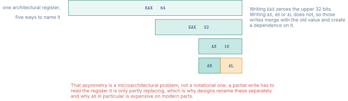
Figure 1 shows the nesting one register accumulated.
General-purpose registers
Long mode defines 16 general-purpose registers (GPRs): RAX, RBX, RCX, RDX, RSI, RDI, RBP, RSP, and R8 through R15. Each is 64 bits wide. The lower 32 bits of each register can be accessed as EAX, EBX, ECX, EDX, ESI, EDI, EBP, ESP, and R8D through R15D. Writing a 32-bit sub-register zero-extends the result into the full 64-bit register, a design choice that avoids false dependencies in the out-of-order pipeline. The lower 16 bits (AX, BX, etc.) and the lower 8 bits (AL, BL, etc.) are also addressable, and writing these narrow sub-registers does not zero-extend, preserving the upper bits for backwards compatibility.
Several GPRs carry implicit roles inherited from the 8086. RCX is the loop counter for the LOOP family. RSP is the stack pointer manipulated by PUSH, POP, CALL, and RET. RAX holds the return value in most calling conventions. RSI and RDI are the source and destination for string instructions (MOVSB, STOSB, CMPSB). These implicit roles are a legacy burden: the compiler must work around them when allocating registers.
The instruction pointer and flags
RIP is the 64-bit instruction pointer. It is not a general-purpose register and cannot be read or written by ordinary ALU instructions. The primary way for code to observe RIP is through RIP-relative addressing, which forms an effective address as RIP plus a 32-bit signed displacement. Position-independent code on x86-64 uses RIP-relative addressing for all global data references, avoiding the need for a link-time relocation.
RFLAGS is the 64-bit flags register. The arithmetic flags (CF, ZF, SF, OF, PF, AF) are set as side effects of ALU instructions and tested by conditional branches. The system flags (IF, TF, IOPL, VM, AC) control interrupt delivery, single-stepping, and privilege-related features discussed in Chapter 20.
SIMD and floating-point registers
The x87 floating-point unit, introduced with the 8087 coprocessor in 1980, provides eight 80-bit registers (ST0 through ST7) organized as a stack. SSE (Streaming SIMD Extensions, 1999) added eight 128-bit XMM registers, extended to sixteen (XMM0–XMM15) in long mode by the REX prefix. AVX (Advanced Vector Extensions, 2011) widened these to 256-bit YMM registers, and AVX-512 (2016) widened them again to 512-bit ZMM registers while doubling the count to 32 (ZMM0–ZMM31). The XMM, YMM, and ZMM names refer to the lower 128, 256, and 512 bits of the same physical register. Chapter 21 covers the vector programming model in detail.
03.Variable-Length Instruction Encoding
The defining feature of the x86 instruction format is that it is variable-length. An instruction can be as short as one byte (the single-byte NOP, opcode 90) or as long as 15 bytes (the architectural maximum). The decoder must parse the byte stream sequentially, examining each byte to determine where the current instruction ends and the next one begins.
Chapter 14 contrasted fixed-length and variable-length encoding in the abstract. Here the concrete encoding comes into focus.
The instruction byte sequence
An x86-64 instruction consists of up to seven fields, all optional except the opcode. In order from the start of the instruction, the fields are:
-
Legacy prefixes (0–4 bytes). Group 1 through Group 4 prefixes modify the behavior of the following instruction. Lock prefix (
F0), repeat prefixes (F2,F3), segment override prefixes, operand-size override (66), and address-size override (67). -
REX prefix (0 or 1 byte, long mode only). Encodes 64-bit operand size, access to registers R8–R15, and access to the uniform low-byte registers (SPL, BPL, SIL, DIL).
-
Opcode (1–3 bytes). The primary opcode byte, or a two-byte opcode starting with
0F, or a three-byte opcode starting with0F 38or0F 3A. -
ModR/M byte (0 or 1 byte). Encodes the addressing mode and up to two register operands.
-
SIB byte (0 or 1 byte). Present when the ModR/M byte specifies the SIB encoding (R/M = 100 with mod 11). Encodes scale, index register, and base register.
-
Displacement (0, 1, 2, or 4 bytes). An immediate offset added to the base address computed by the ModR/M and SIB fields.
-
Immediate (0, 1, 2, or 4 bytes). An immediate operand encoded directly in the instruction stream.
The variable length arises because each field is conditionally present. A register-to-register ADD needs only the REX prefix, the opcode, and the ModR/M byte (three bytes total). A memory reference with a base, an index, a scale, and a 32-bit displacement needs the opcode, the ModR/M byte, the SIB byte, and four displacement bytes (seven bytes before any prefix).
Figure 2 draws the whole envelope, with three real instructions of very different lengths laid on the same byte scale.
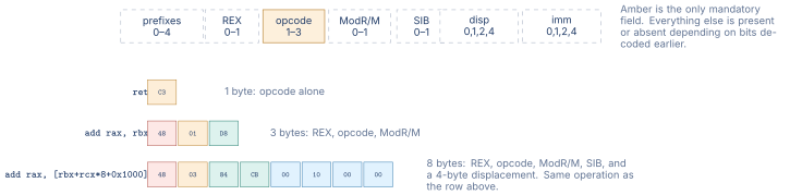
The architectural limit is fifteen bytes. An instruction longer than that raises a general-protection fault rather than executing, which is worth knowing because the limit is not a natural consequence of the encoding. It is possible to write down a byte sequence that decodes coherently and exceeds fifteen bytes, by stacking redundant prefixes, and the processor rejects it anyway. The limit exists so that the fetch hardware has a bound: a decoder must be able to guarantee that an instruction starting in one fetch block ends within a known distance, and without a cap that guarantee cannot be made.
The ModR/M byte in detail
The ModR/M byte is the heart of the x86 addressing scheme. Its eight bits split into three fields:
Table 1. ModR/M byte field layout
| Bits | Field | Width | Meaning |
|---|---|---|---|
| 7–6 | mod | 2 bits | Addressing mode selector |
| 5–3 | reg | 3 bits | Register operand (or opcode extension) |
| 2–0 | r/m | 3 bits | Register or memory operand |
The mod field determines how the r/m field is interpreted. When mod = 11 (binary), r/m names a register and no memory access occurs. When mod = 00, 01, or 10, r/m names a base register (or indicates the SIB encoding), and the mod field selects the displacement size: no displacement (00), 8-bit displacement (01), or 32-bit displacement (10). One combination breaks that pattern. When mod = 00 and r/m = 101, no base register is read and a 32-bit displacement follows instead, taken relative to RIP in long mode and as an absolute address in 32-bit mode.
The three-bit reg and r/m fields can address only eight registers each. This is why the original 8086 and the 80386 had eight GPRs. The REX prefix extends both fields to four bits, raising the count to 16, which is exactly the GPR set of x86-64.
The SIB byte
When the ModR/M byte’s r/m field is 100 (binary) and mod 11, the processor reads a second byte, the SIB byte, to compute the effective address as:
The SIB byte’s three fields are scale (bits 7–6, encoding the values 1, 2, 4, or 8), index (bits 5–3, selecting the index register), and base (bits 2–0, selecting the base register). The scale factor of 1, 2, 4, or 8 matches the size of byte, short, int, and long/pointer array elements, making the SIB encoding a natural fit for array indexing in C.
04.The REX Prefix
The REX prefix is a single byte in the range 0x40–0x4F. Its four low bits are named W, R, X, and B:
Table 2. REX prefix bit fields
| Bit | Name | Function |
|---|---|---|
| 3 | W | 1 = 64-bit operand size |
| 2 | R | Extends ModR/M reg field to 4 bits |
| 1 | X | Extends SIB index field to 4 bits |
| 0 | B | Extends ModR/M r/m field (or SIB base) to 4 bits |
The R, X, and B bits become the high (fourth) bit of the corresponding three-bit field, giving access to registers R8 through R15. REX.W set to 1 promotes the operand size to 64 bits. A plain REX byte (0x40) with all four bits clear still has an effect: it makes SPL, BPL, SIL, and DIL addressable instead of the legacy AH, CH, DH, BH high-byte registers.
The single-byte REX prefix was a pragmatic choice. AMD needed to extend the register file without breaking the existing decoding pipeline, and a one-byte prefix that fit into the existing prefix slot accomplished this with minimal disruption to hardware decoders.
05.VEX and EVEX: AVX and AVX-512 Encoding
The SIMD extensions went through a parallel encoding evolution. SSE instructions used the legacy prefix scheme (a mandatory 66, F2, or F3 prefix before the 0F-prefixed opcode), which limited them to two-operand destructive form: the destination was always the same as one of the sources.
The VEX prefix
Intel’s AVX (2011) introduced the VEX prefix, a compact encoding for three-operand non-destructive instructions. The VEX prefix comes in two forms: a two-byte form (bytes C5 + 1) and a three-byte form (bytes C4 + 2). The three-byte form provides the same register-extension bits as REX, plus a field that selects the implied opcode map (replacing the 0F, 0F 38, and 0F 3A escape bytes) and a field that names the additional source register. The result is that an AVX instruction like vaddps ymm0, ymm1, ymm2 encodes the destination, the first source, and the second source all in the same instruction without destroying either source.
VEX-encoded instructions operate on 128-bit (XMM) or 256-bit (YMM) registers. The upper bits of the YMM register are zeroed when a VEX-128 instruction writes the lower 128 bits, eliminating false dependencies.
The EVEX prefix
AVX-512 (2016) pushed the vector width to 512 bits and required a new prefix to encode the additional state [2]. The EVEX prefix is four bytes and extends VEX with the following capabilities:
-
Access to 32 ZMM registers (ZMM0–ZMM31) through an additional register-extension bit.
-
Eight opmask registers (k0–k7) that provide per-element predication. An EVEX instruction can specify a mask register, and only the lanes where the mask bit is 1 are written. Masked-out lanes are either zeroed (“zeroing masking”) or left unchanged (“merging masking”).
-
Embedded broadcast: a scalar memory operand is broadcast to all vector lanes, avoiding a separate broadcast instruction.
-
Embedded rounding and exception suppression for floating-point instructions.
The progression from legacy SSE through VEX to EVEX illustrates a recurring theme in x86 history: each generation adds encoding machinery to work around limitations in the previous generation, and backward compatibility prevents discarding the older forms.
06.The SIMD Extension Timeline
The x86 SIMD story is a long sequence of incremental additions. Each extension added new data types, new operations, or wider registers, and the existing instructions remained available.
MMX (1997) added eight 64-bit registers (MM0–MM7) aliased to the x87 FP stack, supporting packed 8-, 16-, and 32-bit integer arithmetic. The aliasing with x87 made concurrent floating-point and MMX code painful.
SSE (1999) introduced 128-bit XMM registers and single-precision floating-point SIMD. SSE2 (2001) added double-precision and full integer support on XMM registers, obsoleting MMX. SSE3, SSSE3, and SSE4.1/4.2 added horizontal operations, shuffle refinements, string-processing instructions, and rounding-control instructions.
AVX (2011) widened the registers to 256 bits (YMM), introduced VEX encoding for non-destructive three-operand form, and defined AVX2 (2013) for 256-bit integer SIMD. The FMA3 extension (also 2013) added fused multiply-add for floating-point.
AVX-512 (2016) widened the registers to 512 bits (ZMM), added opmask predication, and shipped in multiple sub-extensions (F, CD, BW, DQ, VL, IFMA, VBMI, VNNI, BF16, FP16, and others) deployed across different processor generations.
AMX (2023) added a matrix-multiply accelerator with eight tile registers (TMM0–TMM7), each configurable as a matrix of up to bytes. AMX targets machine-learning inference workloads and is the first x86 extension that operates on two-dimensional data in a single instruction.
Beyond the SIMD path, Intel and AMD have introduced miscellaneous instruction-set extensions including BMI1/BMI2 (bit manipulation: ANDN, BEXTR, BLSI, BZHI, PEXT, PDEP), F16C (half-precision float conversion), AES-NI (AES encryption rounds), SHA (SHA-1 and SHA-256 acceleration), and CLMUL (carry-less multiplication for GCM and CRC). Each extension added its own CPUID feature flag and its own instruction encodings.
07.The Micro-Op Translation Layer
Chapter 14 introduced the idea that modern x86 processors do not execute CISC instructions directly. Instead, the front-end decoder cracks each x86 instruction into one or more micro-ops (often written ops), and the out-of-order execution engine processes these micro-ops exactly as a RISC pipeline processes fixed-length instructions.
Why micro-ops exist
A variable-length instruction set with hundreds of addressing modes and implicit register usage is difficult to schedule and execute efficiently. The micro-op translation converts the x86 front-end complexity into a uniform internal representation. Each micro-op performs a single register-to-register operation, a single load, or a single store, resembling the simple instructions of a RISC ISA. The back-end pipeline (issue queue, reservation stations, execution units, reorder buffer) does not need to know that the original instruction was a complex CISC operation.
Simple and complex decoders
Modern Intel and AMD processors dedicate multiple decoder slots per cycle. A “simple” decoder handles instructions that translate to a single micro-op. A “complex” decoder (or a microcode sequencer) handles instructions that produce two or more micro-ops. Intel’s public disclosures at the Hot Chips conference have consistently shown four or more simple decoders and one complex decoder per core. AMD’s Zen family uses a similar partitioning.
The decoder also feeds a micro-op cache (Intel calls it the Decoded Stream Buffer, or DSB, and AMD calls it the Op Cache) that stores previously decoded micro-ops indexed by instruction address. When the micro-op cache hits, the decode stage is bypassed entirely, saving power and latency. The micro-op cache is especially effective for tight loops, where the same instruction sequence is fetched repeatedly.
The three paths an instruction can take
Describing the decoders as simple and complex undersells the structure. A modern x86 front end contains three distinct routes from bytes to micro-ops, and which one an instruction takes determines both its throughput and its power cost by a wide margin.
Figure 3 shows all three.
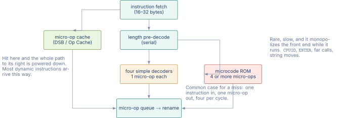
The micro-op cache is the path most instructions actually take. Because it is indexed by address and holds already-decoded micro-ops, a hit skips length pre-decode and the decoders entirely. Loops, which is where dynamic instruction counts concentrate, are served from here after their first iteration.
The simple decoders handle a cache miss for ordinary instructions. Four operate in parallel, each producing one micro-op, so the sustainable rate is four instructions per cycle. This is the path that the length pre-decode stage exists to feed, since the decoders cannot start until the boundaries are known.
The microcode ROM handles the instructions that cannot be expressed in a small number of micro-ops. It is a sequencer rather than a decoder: it reads a stored program and emits micro-ops for several cycles. Crucially, while it runs, the simple decoders are idle, so a single microcoded instruction stalls the entire front end. CPUID, far calls, ENTER, and the string instructions with REP prefixes all go here.
That last point is the practically useful one. The reason optimization guides tell you to avoid a handful of specific x86 instructions is almost never that the instruction is slow to execute. It is that it is microcoded, and a microcoded instruction costs the front end far more than its own latency. An ENTER instruction and the three-instruction sequence that replaces it do the same work, and the three-instruction sequence is faster, because it stays on the fast path.
The cost of translation
The decoder and micro-op cache add transistor area and power consumption that a fixed-length ISA like RISC-V or AArch64 does not need. On the other hand, the variable-length x86 encoding produces smaller binaries (higher code density), which reduces instruction cache pressure and instruction fetch bandwidth requirements. Whether the decode cost or the code-density benefit dominates depends on the workload and the cache hierarchy, and the debate has continued for four decades without resolution.
What is settled is that the micro-op approach works. Intel and AMD ship the highest single-threaded-performance processors in the world, and both rely on micro-op translation as their fundamental execution strategy.
08.The Backwards-Compatibility Burden
The x86 ISA carries every instruction, every addressing mode, and every processor mode defined since the 8086. An x86-64 processor can execute 16-bit real-mode code, 32-bit protected-mode code, and 64-bit long-mode code. The processor mode is selected by the operating system through control-register bits and descriptor-table entries, not by the application.
This compatibility guarantee is both the architecture’s greatest strength and its greatest engineering burden.
What backwards compatibility buys
Software investment is protected. A 64-bit operating system can run 32-bit applications compiled twenty years ago without source changes, recompilation, or emulation. Enterprise software vendors can ship binaries that run on any x86-64 processor from any vendor, confident that the ISA contract will be honored. The installed base of x86 software is the largest in history, and the cost of abandoning that base has defeated multiple attempts to replace x86, including Intel’s own IA-64 (Itanium) and various RISC migration efforts in the 1990s.
What backwards compatibility costs
The encoding space is congested. The single-byte opcode map is fully populated, and new instructions must use multi-byte escape sequences (0F, 0F 38, 0F 3A) or new prefix schemes (VEX, EVEX). The decoder must recognize all of these forms, which increases decoder complexity.
The implicit register roles (RCX for loops, RAX for multiplication output, RDX:RAX for division) reduce the effective number of freely allocable registers. Although x86-64 has 16 GPRs, the compiler cannot use all 16 as freely interchangeable general-purpose storage.
Legacy modes carry their own silicon cost. Real-mode segmentation logic, the x87 FPU stack, the MMX aliasing, and the compatibility sub-mode machinery all occupy area on the die and must be validated against the architectural specification, even though most of these features are rarely exercised in modern workloads.
Why nothing can be removed
The costs above are the visible ones. The structural cost is that x86 has no mechanism for retiring anything, and the reason is worth stating precisely, because it is not that Intel and AMD are sentimental.
Removing an instruction requires knowing that no program uses it. For a platform whose value proposition is that binaries from 1995 still run, that knowledge is unobtainable. There is no registry of x86 binaries, most of the important ones have no surviving source, and the ones most likely to use an obscure instruction, hand-written assembly in installers, copy-protection code, firmware, and old device drivers, are exactly the ones nobody can recompile. An instruction is used until proven otherwise, and the proof cannot be constructed.
The consequence is a ratchet. Every instruction ever added is still present, every addressing mode still decodes, and every mode of operation still boots. A processor released today still powers on in 16-bit real mode and executes the same reset sequence an 80386 did, because the firmware that runs first was written against that behavior.
Two attempts to break the ratchet are instructive because both failed, and they failed differently.
Itanium tried to replace x86 outright with an incompatible architecture, offering emulation for old binaries. The emulation was slow, the native performance depended on compiler technology that did not arrive, and AMD’s decision to extend x86 to 64 bits instead gave the market a way to get 64-bit addressing without leaving. Customers took it.
Intel’s x86S proposal, published in 2023, took the opposite approach: keep the architecture and remove only the modes nothing modern uses, starting the processor directly in 64-bit mode and deleting real mode, 16-bit protected mode and ring 1 and 2. It is a much more modest proposal than Itanium and it targets exactly the machinery that this section describes as dead weight. Whether it ships is still open, and the obstacle is the same one: the firmware and hypervisor ecosystem has to move first, and every part of it has to move before any processor can drop the support.
The endurance of x86
Despite these costs, x86-64 dominates the server, desktop, and laptop markets. The reasons are economic, not technical. The performance of the micro-op translation layer eliminates most of the CISC overhead, and the sheer volume of x86 silicon allows Intel and AMD to amortize the decoder complexity across billions of units. A hypothetical RISC replacement would need to match or exceed x86 performance and run the entire x86 software ecosystem, a combination that no competitor has achieved outside the embedded and mobile spaces where ARM took a different path (see Chapter 16).
09.Encoding Walk-Through: A Concrete Example
To make the encoding machinery concrete, consider the instruction add qword [rbx + rcx*8 + 0x100], rax. This instruction adds RAX to a 64-bit memory operand at address RBX + RCX 8 + 256.
The encoding is:
Byte-level encoding of add [rbx + rcx*8 + 0x100], rax
| 48 01 84 CB 00 01 00 00 | |
| -- -- -- -- ----------- | |
| | | | | +-- disp32 = 0x00000100 (256, little-endian) | |
| | | | +----- SIB: scale=3 (8x), index=1 (RCX), base=3 (RBX) | |
| | | +-------- ModR/M: mod=10, reg=0 (RAX), r/m=4 (SIB follows) | |
| | +----------- Opcode: ADD r/m64, r64 | |
| +-------------- REX.W (0x48): 64-bit operand size |
The total is eight bytes. The REX.W prefix signals 64-bit operand size. The opcode 01 is the ADD variant that stores the result in the r/m operand (memory). The ModR/M byte 84 encodes mod=10 (32-bit displacement), reg=000 (RAX), r/m=100 (SIB follows). The SIB byte CB encodes scale=11 (), index=001 (RCX), base=011 (RBX). The four displacement bytes encode 256 in little-endian order.
A reader accustomed to RISC-V’s clean 32-bit encoding (see Chapter 15) may find this sequence intricate. That intricacy is the price of forty-five years of accumulated encoding decisions, each one constrained by the requirement to leave every earlier encoding undisturbed.
10.x86-64 Compared with RISC-V and AArch64
Table 3. x86-64 compared with RISC-V and AArch64 on key ISA dimensions
| Dimension | x86-64 | AArch64 | RISC-V (RV64GCV) |
|---|---|---|---|
| Encoding length | 1–15 bytes | Fixed 32 bits | 16 or 32 bits |
| GPRs | 16 | 31 + ZR + SP | 32 |
| SIMD registers | 16/32 (XMM–ZMM) | 32 (V0–V31) | 32 (V0–V31) |
| Addressing modes | Many (SIB, disp) | Base + offset | Base + offset |
| Implicit register use | Heavy | Minimal | None |
| Decode complexity | High (variable) | Low (fixed) | Low (fixed) |
| Code density | Highest | Moderate | Moderate |
| Endianness | Little only | Configurable | Little (default) |
The table above summarizes the key structural differences. The comparison is not a judgment of quality: each ISA made different tradeoffs for different markets and different eras. Chapter 22 continues the comparison with a deep dive into the public ISA manuals for all three architectures.
11.Worked Examples
12.Exercises
References
- [1](2024). “AMD64.”
- [2](2024). “Intel.”