State Machines, Arbiters, FIFOs, Flow Control, and CAMs
September 8, 202623 min readadvanced
Almost every "design a block that does X" whiteboard question resolves into four things.
01.Part 1, the four structures
Almost every "design a block that does X" whiteboard question resolves into four things.
A state machine decides what to do next. An arbiter resolves competition when several things want one resource. A FIFO decouples a producer from a consumer so they need not agree cycle by cycle. A flow control protocol stops one side overrunning the other.
Learn these four properly and most such questions become assembly rather than invention. That is genuinely how experienced designers approach a blank whiteboard, by recognizing which of a small set of known structures the problem decomposes into.
02.Part 2, state machines
2.1 What a state machine is, from scratch
Suppose you want a circuit that watches a stream of bits arriving one per clock cycle, and raises an output whenever it has just seen the pattern 1, 0, 1.
Try to do it with combinational logic alone and you immediately fail, because combinational logic sees only the present input. It has no way to know that the two previous bits were 1 and 0. You need memory, which from Digital Logic and Timing means flip-flops, which means this is sequential logic.
But what exactly do you need to remember? Not the entire history, that would need unbounded storage. You only need to remember how much of the pattern you have matched so far, which is a small, finite amount of information.
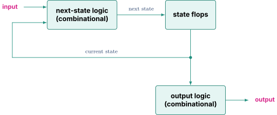
That quantity, "how much of the pattern have I matched," is the state. A finite state machine is a circuit that holds a state in flip-flops, computes a next state from the current state and the input, and produces an output.
Every FSM has exactly three pieces.
2.2 The Moore version, worked
In a Moore machine, the output depends only on the current state. So you need a state whose meaning is "I have just completed the pattern."
Work out what you need to remember.
- Nothing useful seen yet. Call it S0.
- Just seen a 1, which could start the pattern. Call it S1.
- Seen 1 then 0, so two thirds of the way. Call it S10.
- Seen 1 then 0 then 1, pattern complete. Call it S101.
Now fill in the transitions by asking, for each state and each possible input, what is the longest prefix of the pattern I have now matched?
| State | Meaning | Input 0 goes to | Input 1 goes to | Output |
|---|---|---|---|---|
| S0 | nothing matched | S0 | S1 | 0 |
| S1 | seen 1 | S10 | S1 | 0 |
| S10 | seen 10 | S0 | S101 | 0 |
| S101 | seen 101 | S10 | S1 | 1 |
Two transitions deserve a second look because they are where beginners make mistakes.
From S1 on input 1, go back to S1, not to S0. You saw 1 then 1. The first 1 is useless now, but the second 1 is a perfectly good start to a new pattern, so you have matched one character, which is S1.
From S101 on input 0, go to S10, not S0. You matched 101 and then saw 0. Look at the last two characters received, which are 1 and 0. That is exactly the prefix "10", so you are in S10. This is what allows overlapping matches, and forgetting it is the classic bug.
Trace the input starting from S0.
| Bit | Input | State before | State after | Output during |
|---|---|---|---|---|
| 1 | 1 | S0 | S1 | 0 |
| 2 | 0 | S1 | S10 | 0 |
| 3 | 1 | S10 | S101 | 0 |
| 4 | 1 | S101 | S1 | 1 (was in S101) |
| 5 | 0 | S1 | S10 | 0 |
| 6 | 1 | S10 | S101 | 0 |
The output is 1 during the cycles when the state is S101, so it fires twice as expected. Notice the output appears one cycle after the completing bit, because the state must be captured by the flops before the output logic sees it.
2.3 The Mealy version, and the real trade
In a Mealy machine, the output depends on the current state and the current input. That changes things, because you can assert the output on the transition itself rather than needing a state to remember that you finished.
| State | On input 0 | On input 1 |
|---|---|---|
| S0 | go S0, out 0 | go S1, out 0 |
| S1 | go S10, out 0 | go S1, out 0 |
| S10 | go S0, out 0 | go S1, out 1 |
Three states instead of four, and the output fires one cycle earlier, at the same moment as the completing bit rather than the cycle after.
That sounds strictly better and it is not. Here is the trade, stated precisely.
Moore advantages. The output comes straight out of a flip-flop, so it is registered, meaning it is glitch-free and its timing is trivially predictable. Downstream logic gets a full clock period to use it.
Mealy advantages. Fewer states, less logic, and one cycle less latency.
Mealy costs. The output is combinational from the input, so it glitches, exactly as the adder did in Digital Logic and Timing. Worse, it creates a combinational path running from an input pin straight through to an output pin, which appears in timing analysis and eats into the budgets of both the upstream and downstream blocks. Worst of all, if two Mealy machines face each other, with A's output feeding B's input and B's output feeding A's input, you can create a combinational loop, which is a circuit with no defined value and which will simply hang.
The practical rule most teams follow is to use Moore for anything crossing a module boundary and allow Mealy inside a block where you control both ends. When in doubt, register the output.
2.4 State encoding
The state is stored in flops, so you must choose how to represent, say, four states as bits.
Binary encoding uses flops, so 2 flops for 4 states, giving S0 = 00, S1 = 01, S10 = 10, S101 = 11. Minimum flops and minimum area. The cost is that testing "am I in S101" requires decoding, an AND of two bits, and next-state logic tends to be deeper.
One-hot encoding uses one flop per state, so 4 flops, with exactly one high at a time. S0 = 0001, S1 = 0010, S10 = 0100, S101 = 1000. Testing "am I in S101" is now a single wire, requiring no logic at all. Next-state logic is shallow and fast. The cost is more flops.
The tradeoff flips depending on state count. For a handful of states, one-hot is usually faster and barely larger. For dozens of states, binary wins on area decisively. Most synthesis tools choose automatically and let you override.
Gray encoding changes exactly one bit between consecutive states. It matters when the state value must cross into another clock domain, for the reason explained in Clocking Reset and Domain Crossing, and it is what makes asynchronous FIFO pointers work.
03.Part 3, arbiters
3.1 The problem
Three blocks all want to use one memory port. Only one can go per cycle. Something must choose. That something is an arbiter.
An arbiter takes request signals and produces grant signals, with at most one grant asserted at a time, and asserting a grant only to a requester that actually requested.
This sounds trivial and it is not, because which requester you choose has consequences that compound over time.
3.2 Fixed priority, and how it fails
The simplest arbiter says requester 0 beats 1 beats 2. In logic, grant 0 if request 0. Grant 1 if request 1 and not request 0. Grant 2 if request 2 and neither of the others. That is a priority encoder and it is small and fast.
Now run it with all three requesting continuously, which is a completely normal situation when three cores share a memory port under load.
| Cycle | Requests | Grant |
|---|---|---|
| 1 | R0, R1, R2 | R0 |
| 2 | R0, R1, R2 | R0 |
| 3 | R0, R1, R2 | R0 |
| ... | ... | R0 forever |
Requesters 1 and 2 never get service. Not slowly, not eventually. Never.
That is starvation, and it is a correctness-level failure even though every individual grant was legal. A system where one agent can be locked out indefinitely is broken, and it usually manifests as a hang or a timeout in some far-away piece of software.
Fixed priority is acceptable only when you can prove the high-priority requester is intermittent, for example an error-handling path that fires rarely.
3.3 Round robin
The fix is to rotate who has top priority. After granting requester , make requester the highest priority for the next decision.
Same scenario, all three requesting continuously.
| Cycle | Priority starts at | Grant |
|---|---|---|
| 1 | R0 | R0 |
| 2 | R1 | R1 |
| 3 | R2 | R2 |
| 4 | R0 | R0 |
| 5 | R1 | R1 |
Each requester gets exactly one third of the bandwidth. No starvation, and the allocation is fair.
Round robin also has a property worth naming. It is work-conserving, meaning it never idles the resource while someone wants it. If only R0 and R2 are requesting, the sequence is R0, R2, R0, R2, and R1's turn is simply skipped rather than wasted.
How to build it. The standard implementation keeps a pointer to the highest-priority requester and uses a mask and find first approach. Mask off all requests below the pointer, find the first remaining request, and if none remain, wrap around and find the first request from the beginning. In hardware that is two priority encoders and a mux, which is why it is only slightly more expensive than fixed priority. Being able to sketch this is a common interview ask.
3.4 Matrix arbiters
Round robin's rotation is fixed, which can still be unfair in a subtle way. A requester that just got served may get served again before one that has been waiting longer, depending on where the pointer happens to be.
A matrix arbiter implements true least-recently-granted ordering. Keep an matrix of bits where entry means "requester has priority over requester ." Grant the requester that no other active requester beats. Then update the winner's row to all zeros and its column to all ones, which pushes it to lowest priority.
This gives exact LRU fairness at a cost of bits and the associated update logic, so it is used where round robin's approximation is not good enough, typically in memory controllers and interconnect switches.
3.5 The two properties to name
Fairness means every requester is eventually served. Round robin and matrix arbiters have it, fixed priority does not.
Forward progress is stronger and system-level. It means the system as a whole always makes progress, which requires that no set of arbiter decisions creates a cycle where everyone waits for everyone else. That is the deadlock discussion in Part 6.
04.Part 4, FIFOs
4.1 Why decoupling matters
A producer generates data and a consumer uses it. If they must agree cycle by cycle, then every hiccup on either side stalls the other, and the two blocks become tightly coupled in a way that makes both harder to design.
A FIFO, first in first out, sits between them as a buffer. The producer writes whenever it has data and the FIFO is not full. The consumer reads whenever it wants data and the FIFO is not empty. Neither needs to know anything about the other's timing.
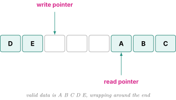
Physically it is a small memory plus two pointers. A write pointer says where the next write goes. A read pointer says where the next read comes from. Both advance and wrap around, which is why this is a circular buffer.
4.2 How deep, worked properly
"How deep should the FIFO be" is a real design question with a real answer, and guessing is not it.
Set up a concrete case. The producer emits a burst of 16 words at one per cycle, then idles for 16 cycles, repeating. The consumer drains steadily at one word every 2 cycles.
Step 1, check the average rates. Over one full 32-cycle period the producer delivers 16 words. The consumer, at one per 2 cycles for 32 cycles, removes 16 words. The rates match, so the FIFO does not grow without bound. Good, the system is stable. If the producer's average exceeded the consumer's, no depth would be enough and you would need backpressure or a faster consumer.
Step 2, find the peak occupancy. Stability is not enough, because the burst is uneven. During the 16-cycle burst, the producer writes 16 words while the consumer reads only 8. So occupancy climbs by 8 during the burst, then drains back down during the idle period.
Step 3, add margin. Real designs round up, both for safety and for the reason in 4.4 below.
The generalizable lesson is that FIFO depth is set by burstiness, not by average rate. Average rate determines whether the system works at all. Burst behavior determines how much buffering it needs.
4.3 Full and empty, the classic trap
Both conditions look identical, because in both cases the read and write pointers are equal. Start empty with both at 0. Write 8 words into an 8-deep FIFO and the write pointer wraps back to 0. Now both pointers are 0 again, and the FIFO is full. Pointer equality alone cannot tell you which.
Two standard fixes.
Extra bit. Make each pointer one bit wider than needed to address the memory. For an 8-deep FIFO use 4-bit pointers instead of 3. The low 3 bits address the memory and the extra bit acts as a wrap counter. Now, if the pointers are equal including the extra bit, the FIFO is empty. If the low bits are equal but the extra bits differ, exactly one more wrap has occurred on the write side, so the FIFO is full. This is elegant and is what asynchronous FIFOs use, since it works with gray-coded pointers.
Occupancy counter. Keep a separate counter incremented on write, decremented on read. Empty is count equal to zero, full is count equal to depth. Simpler to reason about, and it costs an extra adder and does not translate cleanly across clock domains.
4.4 Almost-full and almost-empty
In a real design the full signal does not reach the producer instantly. It goes through a register or two for timing, and the producer's decision logic takes a cycle. So by the time the producer sees "full" and stops, it may already have sent several more words.
If the producer needs cycles to react, you must assert almost-full when there are still free entries, not when there are zero. Otherwise you overflow and lose data silently, which is one of the nastier bugs to find because the FIFO logic itself looks correct.
The same reasoning applies in reverse for almost-empty on the consumer side.
05.Part 5, flow control
5.1 Valid and ready
This is the dominant modern convention and it is what AXI uses, covered in Interconnect and AMBA.
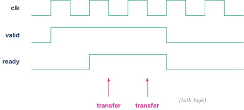
The sender asserts valid when it has data on the bus. The receiver asserts ready when it is able to accept. A transfer happens on any cycle where both are high, which makes the protocol trivially composable and easy to pipeline.
5.2 The one rule that gets asked
valid must not depend combinationally on ready.
The reason is a deadlock. The sender must be able to decide "I have data" without knowing whether the receiver will take it. If the sender waits to see ready before asserting valid, and the receiver waits to see valid before asserting ready, then neither ever asserts and the link is dead. Worse, in RTL this creates a genuine combinational loop, which simulators may report as an error or may simply oscillate on.
The asymmetry is deliberate and it is allowed in one direction only. The receiver may make ready depend on valid, for example only accepting when it sees something worth accepting. The sender may not do the reverse.
If you need the sender to wait, the correct structure is a skid buffer, a small two-entry buffer that absorbs the in-flight word when the receiver deasserts ready, allowing full throughput without a combinational path.
5.3 Request and acknowledge
The older handshake. The sender raises req, the receiver raises ack, the sender drops req, the receiver drops ack. That is a four-phase handshake and it costs a full round trip per transfer, so throughput is poor.
It survives mainly for clock domain crossings, where the round trip is unavoidable anyway because each direction must pass through synchronizers, as covered in Clocking Reset and Domain Crossing.
5.4 Credit-based flow control
This inverts the problem and is worth understanding because it is how every serious interconnect works.
Instead of the receiver saying "stop" when it is full, the receiver tells the sender up front how many buffer slots it has. The sender keeps a credit counter, decrements it on each send, and stops when it hits zero. As the receiver frees space, it returns credits.
The advantage is decisive when the two ends are far apart. With valid and ready, the sender must wait for a backpressure signal to travel back, and if that takes 10 cycles the sender must either stop early or risk overflow. With credits, the sender knows in advance exactly how much it may send, so it can keep the pipe full continuously.
The sizing rule is Little's law again. To keep a link busy with round-trip latency and one word per cycle, you need at least credits, because that is how many words are in flight before the first credit returns.
06.Part 6, deadlock, livelock, starvation
Cache-focused roles name "starvation and deadlock avoidance" explicitly, so be precise about the three. They are commonly confused and they have different fixes.
6.1 Starvation
One requester never gets served while others do. The system as a whole is making progress, just not for that one agent. Fix, arbiter fairness, as in Part 3.
6.2 Deadlock
A cycle of dependencies where every party is waiting for another, and nothing moves, permanently. This is total system failure, not slowness.
The classic on-chip case. Buffer A is full and its drain path needs a response that must travel through buffer B. Buffer B is full and its drain path needs a response that must travel through buffer A. Neither can drain, so neither ever will.
Three standard fixes.
Ordered acquisition. Require that resources be acquired in a fixed global order. A cycle requires someone to acquire out of order, so if nobody ever does, no cycle can form. This is the same idea as lock ordering in software.
Guaranteed drain path. Ensure that at least one path can always make progress without depending on the blocked resource. Often this means reserving a buffer entry that only the drain traffic may use.
Virtual channels. Share the physical wires but keep separate buffers per message class. If requests and responses have independent buffers, a full request queue cannot block the responses needed to drain it, so that particular cycle cannot form. This is the standard answer in interconnect design and it is covered further in Interconnect and AMBA.
6.3 Livelock
Motion without progress. Everything is busy, requests are issued and retried constantly, and yet no work ever completes.
The canonical hardware example is two cores repeatedly stealing a cache line from each other. Core A gets the line, starts its operation, loses the line to core B before completing, requests it back, and so on forever. Both cores are 100 percent busy and neither finishes. This connects to Cache Coherence Protocols.
Fixes involve backoff, priority escalation with waiting time, or forward-progress guarantees that let a requester complete once it has failed enough times.
07.Part 7, content addressable memory
7.1 The reverse of a memory
A normal memory answers "what is stored at address 5?" A CAM answers the reverse question, "is the value 0x4A stored anywhere, and if so where?"
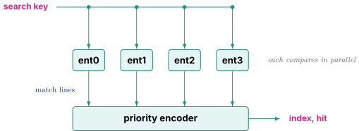
The implementation is direct. Every entry holds a stored value and comparison logic. On a search, the key is broadcast to all entries simultaneously, every entry compares in parallel, and the entries that match assert a match line. A priority encoder converts the match lines into an index.
7.2 Why CAMs are always small
That parallel comparison is why CAMs are fast, and it is exactly why they are expensive.
Area. Every cell contains comparison logic in addition to storage, so a CAM cell is roughly twice the size of an SRAM cell or more, as covered in SRAM Arrays and ECC.
Power. Every search activates the entire array, since every entry must compare. There is no way to activate only part of it, because you do not know where the match is, that is the whole point. So CAM search energy scales with total capacity, not with the number of matches.
Timing. The match lines are long wires spanning the array, and the priority encoder adds depth.
That cost profile produces a rule you can state confidently in an interview. Any structure in a CPU that is searched associatively by content will be small, because CAM cost grows fast and unavoidably.
7.3 Where CAMs appear in a CPU
This list is worth memorizing because it explains several structure sizes you will meet later.
Fully associative TLBs search by virtual page number, from Virtual Memory and Memory Ordering.
Load and store queues search by address for store-to-load forwarding, from Load Store and Memory Ordering. That is why they hold tens of entries and not hundreds.
Issue queue wakeup compares broadcast result tags against every waiting operand, from Out of Order Execution. That is why issue queues are tens of entries while reorder buffers, which are not CAMs, are hundreds.
Cache tag comparison in a set-associative cache is a small CAM across the ways of one set.
Being able to say "issue queues are small because wakeup is a CAM and CAM cost grows with entries times width" is a causal explanation rather than a memorized fact, and that difference is what interviewers listen for.
7.4 Ternary CAM
A TCAM adds a third per-bit state, don't care, alongside 0 and 1. That allows prefix matching, where a stored entry of 1010xxxx matches any key beginning with 1010. Routers use this for longest-prefix-match IP lookup. TCAM cells are larger still and are rare inside CPUs.
08.Part 9, check yourself
- Why can a pattern detector not be built from combinational logic alone? What exactly must be remembered? (2.1)
- In the 101 detector, why does S101 on input 0 go to S10 rather than S0? (2.2)
- Convert a Moore machine to Mealy. State precisely what you gained and what you lost. (2.3)
- When would you choose one-hot encoding over binary, and why does the answer depend on state count? (2.4)
- All four requesters ask every cycle under fixed priority. What happens, what is it called, and why is it a correctness problem rather than a performance one? (3.2)
- Sketch a round robin arbiter. How does mask-and-find-first work? (3.3)
- What does work-conserving mean and why does round robin have that property? (3.3)
- A producer bursts 32 words at one per cycle then idles 32. The consumer takes one word every 4 cycles. Is the system stable? How deep must the FIFO be? (4.2)
- Why is pointer equality insufficient to distinguish full from empty? Give two fixes and say which works across clock domains. (4.3)
- Why does almost-full exist, and what happens if you size it wrong? (4.4)
- Why must
validnot depend onready? What is a skid buffer for? (5.2) - What does credit-based flow control buy you that valid and ready does not? (5.4)
- Distinguish starvation, deadlock, and livelock, with a concrete hardware example of each and the fix for each. (6)
- Explain precisely how virtual channels break a deadlock cycle. (6.2)
- Why are all associatively-searched structures in a CPU small? Give three examples. (7.2, 7.3)
09.Part 10, related notes
- Digital Logic and Timing for the flops and timing these are built from
- Interconnect and AMBA for these structures at network scale, and virtual channels in context
- Cache Coherence Protocols for real deadlock and livelock cases in a protocol
- Out of Order Execution for issue queue wakeup as the CPU's most performance-critical CAM
- RTL Design and SystemVerilog for actually coding the FIFO and arbiter