Interconnect, NoC, and AMBA Protocols
September 8, 202645 min readadvanced
Latency is cycles across an empty network, dominated by hop count, since each hop costs at least a cycle of arbitration plus a cycle of wire.
01.Part 1, the problem the interconnect solves
1.1 Wire everything to everything and watch it fail
A modern SoC has four CPU clusters, a GPU, a neural engine, an ISP, a video encoder, a display controller, DMA engines, memory controllers, a security block. Call the count . Any of them may need memory another one owns.
The obvious design gives every pair private wires. No contention, one hop. How many wires? The number of unordered pairs of things is
At that is 120 links, at it is 2016. A useful link carries 128 bits each way plus address, control, and handshake, call it 350 wires. So 120 links is 42,000 wires and 2016 links is 705,600 wires, each consuming a metal track along its whole length. You run out of metal long before transistors.
The second failure is worse. Each agent needs ports, so at every block has 63 interfaces to design, verify, power-manage, and time-close, and adding a 65th block means touching all 64. The design does not compose.
So the field exists to answer one question. How do you let agents talk without paying in wires and without redesigning everybody when you add one?
1.2 The three numbers you argue with
Latency is cycles across an empty network, dominated by hop count, since each hop costs at least a cycle of arbitration plus a cycle of wire.
Cost is area and metal. Routers cost gates and buffers, links cost tracks, and the two trade in ways that surprise people.
Bisection bandwidth needs building up. Cut the network into two halves with equal agent counts. Many cuts exist, so pick the one severing the fewest links, since that is the weakest point. Add the bandwidth of everything cut. That is the bisection bandwidth.
Why it matters. If every agent sends to a random other agent, half the destinations are on the far side of any equal cut, so half of all traffic crosses the bisection. With agents each injecting one transfer per cycle, must cross. If the bisection carries 4, the rest queue no matter how clever the routers are. Bisection bandwidth is a hard ceiling that routing cleverness cannot lift. That is why the industry moved from rings to meshes.
02.Part 2, topologies with the numbers worked
Work each at and , because the ranking changes between them.
2.1 The shared bus
One wire bundle, everybody connected, an arbiter picking one driver per cycle.
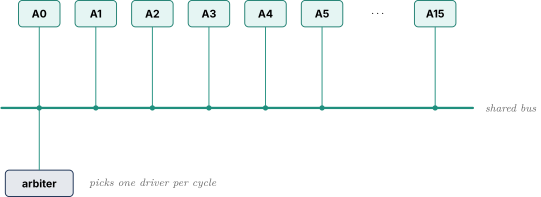
Cost is . Latency is one hop, genuinely better than any mesh at small . Bisection is 1 transfer per cycle regardless of , since cutting the bus anywhere severs one link. So at , against a demand of 8, the bus meets 12.5 percent. At , against 32, it meets 3.1 percent.
There is a physical problem on top. A bus wire runs past every agent, so it is long, and every driver hangs off it, so its capacitance is enormous. Per Digital Logic and Timing, delay tracks capacitance, so a bus gets slower as you add agents as well as more congested.
2.2 The crossbar
Every input reaches every output at once, provided no two want the same output.
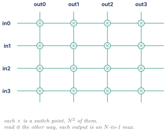
Bisection is , exactly the demand, and latency is one hop, so a crossbar is ideal on both. Cost is where it dies, and it is worth counting rather than waving at . Each output is an -to-1 mux per data bit, and an -to-1 mux costs about two-to-one muxes at roughly 3 gates each, so with 128 bits the gates per output are .
| Gates per output | Outputs | Total switch gates | |
|---|---|---|---|
| 16 | 16 | ||
| 64 | 64 |
Four times the agents costs nearly seventeen times the switch. Wiring is worse. A crossbar needs horizontal tracks crossing vertical. At , that is 2048 by 2048, which on a 100 nm pitch is about mm². At it is 8192 by 8192, about mm², pure metal before a transistor. Crossbars are wire-limited, and wires scale badly.
Crossbars are right small and impossible large. Real chips use them constantly, at 4 to 8 ports inside a cluster or inside a router.
2.3 The ring
Agents in a loop with small three-port routers, messages hopping until they arrive.
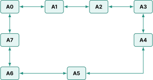
Cost is and every link is short, reaching only the physical neighbour. Short links are cheap in metal and fast in delay, a real advantage complexity notation hides.
Count hops properly. On a bidirectional ring the distances from any node are 1, 1, 2, 2, up to appearing once. At the sum is , so the average is . At it is , average . Both land on the familiar rule, and the point is what happens between them. Ring latency is linear in , and 16 hops at a cycle each is 16 cycles on every miss.
Bisection needs two cuts to split a loop, so 2 links or 4 unidirectional channels, constant and independent of . Intel shipped rings in servers for many generations and moved off them for exactly these two numbers.
2.4 The mesh
A grid with , five-port routers, travel in then .

The average Manhattan distance between random points on a line of positions is , and a mesh has two dimensions, so
At that is hops, at it is . That is , and the contrast is the whole argument. At the mesh saves 4.27 against 2.5, nice but not decisive. At it is 16.25 against 5.25, a factor of three. The mesh wins not by being better small but by degrading more slowly. Bisection severs links, so it grows, which the ring's never did.
Now a number that surprises people. A five-port router with 128-bit links, 4 virtual channels per port and 4 flits per channel holds flops, roughly 61,000 gate equivalents, plus about 7,700 gates of internal muxing and some arbiters. Call it 70,000 gates. Sixty-four of them is 4.5 million gates, more than the 64-port crossbar's 1.55 million.
Say that out loud in an interview, because it shows you did the arithmetic. The mesh is not cheaper in gates. It wins because every wire is short and local so it times close easily, because the design is one tile replicated so physical-design effort does not grow with , and because bisection grows with .
2.5 Side by side
| Bus | Crossbar | Ring | Mesh | |
|---|---|---|---|---|
| Switch cost | ||||
| Wire lengths | global, long | global, dense | local, short | local, short |
| Avg hops, | 1 | 1 | 4.27 | 2.5 |
| Avg hops, | 1 | 1 | 16.25 | 5.25 |
| Bisection channels | 1 | 4, constant | ||
| Bisection, | 1 | 8 | 4 | 8 |
| Bisection, | 1 | 32 | 4 | 16 |
| Demand, | 32 | 32 | 32 | 32 |
| Percent met, | 3 | 100 | 12.5 | 50 |
That last row is the history of on-chip interconnect in one line. A real SoC uses all four at once. A crossbar inside a four-core cluster where latency is precious, a mesh or ring joining clusters and GPU and memory controllers, a bus for register configuration where bandwidth does not matter. Choosing the cheap topology where it suffices is as much of the skill as knowing the expensive one.
03.Part 3, packets, flits, and how they move
3.1 From message to flit
A CPU misses in L2 and fetches a 64-byte line from a memory controller four hops away. The reply carries 64 bytes plus a header saying who it is for, what transaction it answers, and what coherence state it grants. Call the header 16 bytes. That 80-byte thing is a packet, and it travels intact end to end.
The link is not 80 bytes wide, because 640 wires per direction would eat the die. Say 16 bytes. A flit, flow control unit, is the piece that fits, and it is the granularity at which buffers are allocated and credits counted. Here the packet is 5 flits. A phit is what physically crosses the wire in one cycle, often the same size, and you can usually ignore it.
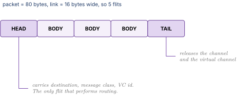
The head flit is the only one that decides anything. On arrival the router computes an output port, arbitrates, and records the decision. Body flits follow the recorded path blindly. The tail flit carries the last payload and tears the path down on its way out. That is what makes routers cheap, since only one flit in five does any thinking.
3.2 Three ways to move a packet
When a head flit arrives, may the router forward before the rest lands? Store-and-forward says no, buffer it all then send. Wormhole says yes immediately, so body flits stream behind the head while the tail is still routers back, the packet stretched across the network like a worm. Virtual cut-through forwards immediately but only allocates an output when the next router has room for the whole packet, so a blocked packet is absorbed into one router rather than draped across four.
Work the 5-flit packet over 4 links at a cycle per hop.
| Event | Store-and-forward | Wormhole |
|---|---|---|
| clears router 1 | 5, waits for all 5 flits | 2 |
| clears router 2 | 10 | 3 |
| clears router 3 | 15 | 4 |
| packet complete | 20 | 8 |
The general forms are and for hops and flits. Buffering is the bigger difference. Store-and-forward needs a full packet, 5 flits, per port per virtual channel. Wormhole needs 1 or 2. Since buffers dominate router area per 2.4, cutting depth by five is a large win.
3.3 What wormhole costs
A wormhole packet occupies buffers in several routers at once, and if the head blocks, all of them stay occupied. One blocked packet holds channels hostage across a chain of routers that have nothing to do with the blockage.
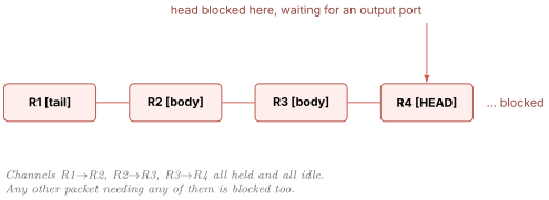
That is why wormhole and deadlock are always discussed together. Virtual cut-through avoids the spanning problem but costs a full packet of buffering per channel, which is exactly what wormhole was avoiding.
04.Part 4, deadlock and virtual channels
4.1 Deadlock, drawn
Deadlock is a set of packets stuck forever because each holds a resource the next needs, in a closed loop. Nothing is broken, no error is signalled, the network simply stops. Unless you built a watchdog you find out from a hang in silicon at 3 a.m.
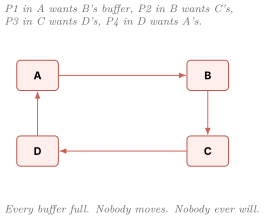
Four conditions must all hold, and the vocabulary gets used in interviews. Mutual exclusion, a buffer is held by one packet. Hold and wait, a packet keeps what it has while asking for more. No preemption, you cannot yank a buffer away. Circular wait, the waits-for relation has a cycle.
Break any one and deadlock is impossible. Preemption is impractical on chip because it means dropping packets and retransmitting, which needs end-to-end sequence numbers and retry buffers. So on-chip networks break circular wait.
4.2 The protocol-level cycle, stated precisely
The square is the version people draw. The version that bites you involves no topology at all.
Two coherent caches A and B share a network, each with an inbound queue of 4 requests. A's queue is full. To make progress A must process a request, and processing means sending a response. That response must enter the network, but the network's buffers are full of requests headed toward queues like A's that are also full. Those requests cannot be delivered because A's queue is full. A's queue cannot drain because draining requires sending a response. The response cannot be sent because the network is full of requests.
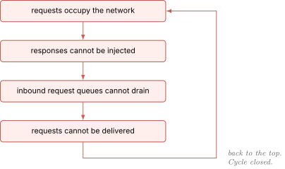
Nothing is wrong with the topology. This deadlock happens on a crossbar. It happens on a bus. It comes purely from requests and responses sharing a buffer pool.
The essential asymmetry is that a request generates more traffic when consumed, so consuming one does not guarantee progress, while a response generates nothing, because the requester reserved a slot for it when it issued the request. Mixing them in one pool destroys that asymmetry.
4.3 Virtual channels, and exactly why they fix it
A virtual channel is a separate set of buffers at every router sharing the same physical wires. With 4 VCs, arriving flits sort into 4 independent queues, and each cycle the router picks one non-empty, non-blocked VC and sends a flit.
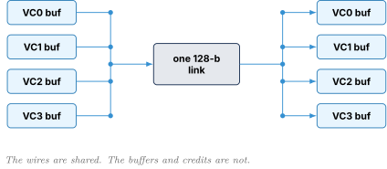
Put requests on VC0 and responses on VC1, never the reverse. Redo 4.2. A sends its response on VC1, whose buffers contain no requests and never can.
Is VC1 guaranteed to drain? Yes, and this is the load-bearing step. A response terminates at a node that already reserved space for it. When A issued its original request it allocated a tracking entry, an MSHR in cache terms, and that entry is the reserved landing spot. So the destination always accepts the response, VC1 always drains, the response gets through, A's request queue drains, requests move.
As a graph, requests depend on responses since a request cannot retire until a response is sent, and responses depend on nothing. That is acyclic, and an acyclic dependency graph cannot deadlock. The virtual channels are what make the classes physically independent so the graph is honest.
Real coherence adds a wrinkle. A read arrives at the home node, which sends snoops to sharers, which send snoop responses, after which the home sends data.
Four classes, so four virtual channels, and traffic may only move to a strictly later class. That is why CHI defines four message classes, per 6.9. Any implementation letting a snoop share buffers with a request has reintroduced the cycle.
VCs buy two other things. They break head-of-line blocking, where a stuck packet at the front of a queue blocks one behind it that could move. And they give QoS classes somewhere to live, per Part 5.
4.4 Dimension-ordered routing, and why it is provably deadlock free
VCs handle the protocol cycle. The topology cycle needs a different fix, and the cheapest is forbidding the turns that could close a loop.
Dimension-ordered routing, XY in a 2D mesh, is one rule. Travel in until the column is right, then in until the row is right, and never travel in again. From to the path is , four hops, equal to the Manhattan distance, so minimal.
| ALLOWED under XY FORBIDDEN under XY | |
| X+ then Y+ Y+ then X+ | |
| X+ then Y- Y+ then X- | |
| X- then Y+ Y- then X+ | |
| X- then Y- Y- then X- | |
| Every X-to-Y turn is permitted, no Y-to-X turn is. |
Now the proof. Build the channel dependency graph, whose nodes are physical channels, with an edge from to if some packet might hold while waiting for . A network deadlocks only if that graph has a cycle.
Under XY, a packet on an X channel may next want another X channel further along the same row, or a Y channel. A packet on a Y channel may next want another Y channel further along the same column and nothing else, because Y-to-X is forbidden. No minimal path reverses direction, so a packet using channels never touches an channel.
Number the channels with all first ordered left to right, then all right to left, then all bottom to top, then all . Under that numbering every dependency edge points from lower to higher. A cycle needs at least one edge pointing down. There is none. No cycle, so no deadlock, without a single extra virtual channel.
That is what "provably deadlock free" means. Not a claim about test coverage, a structural argument about a graph.
4.5 Adaptive routing and escape channels
XY is rigid. If the direct row is congested and a parallel row is empty, an XY packet sits in the jam anyway. Adaptive routing lets the router choose among legal ports by congestion, usually from downstream credit counts. Minimal adaptive routing chooses only ports that reduce distance. Non-minimal may move away from the destination to escape a hot spot, buying flexibility and risking livelock, where a packet moves forever without arriving.
The problem is that adaptivity reintroduces Y-to-X turns, so the graph argument collapses. The fix is Duato's protocol. Provide virtual channels for unrestricted adaptive routing, plus at least one escape channel routed strictly dimension-ordered. A packet hops freely among adaptive VCs, and whenever it cannot make progress it may drop into the escape VC, where 4.4 guarantees arrival. The network is deadlock free because it always contains a deadlock-free subnetwork any stuck packet can fall into.
| Failure | What is happening | Typical fix |
|---|---|---|
| Deadlock | packets stuck forever in a cycle, no motion | VCs, turn restrictions, escape channels |
| Livelock | packets moving forever, never arriving | minimal routing, or force minimal after misroutes |
| Starvation | one packet keeps losing arbitration while others proceed | round robin, or age-based priority |
Starvation is the one an RTL designer meets most, and it is an arbiter problem rather than a network one, so it belongs to Arbiters FIFOs and CAMs.
05.Part 5, quality of service
5.1 Two clients with opposite needs
A display controller feeds a 4K panel, 3840 by 2160 pixels at 4 bytes each, 60 times a second.
About 2 GB/s, and here is the crucial part. Not 2 GB/s on average with freedom to burst. The panel's timing controller demands pixels on a schedule the SoC does not control. The display block buffers ahead in a small FIFO, take 8 KB.
At 1 GHz that is about 4,100 cycles of slack. Miss it and the display underruns and the user sees a torn line or a black flash. There is no recovery. You cannot retry a pixel that was due three microseconds ago.
A CPU taking a load miss also wants data, but 200 extra cycles just means the program runs slightly slower and nobody sees anything. A CPU prefetch is weaker still, a guess about the future, and dropping it is a legitimate design choice.
| Display refill | CPU demand miss | CPU prefetch | |
|---|---|---|---|
| Bandwidth | 2 GB/s, steady | bursty | bursty |
| What it needs | bounded latency | low latency | nothing in particular |
| Deadline | hard, ~4,100 cycles | none | none |
| Failure mode | visible tear, unrecoverable | slightly slower program | nothing |
| Droppable | never | no | yes |
Read the two middle rows together, because that is what people miss. The display does not need low latency, it needs bounded latency. Ten thousand cycles of consistent latency is fine if the bound is known and the FIFO sized for it. The CPU is the opposite, wanting latency as small as possible with no hard bound at all. Two clients that both want good service want opposite things, and one priority number cannot express that.
5.2 The mechanisms, cheapest first
Static priority. Always serve the highest non-empty class. One priority encoder, and one fatal property, since a saturating high class starves everything below it completely. Acceptable only when the high class is provably rate-bounded.
Weighted arbitration. Weighted or deficit round robin serves classes in proportion. Weights of 3 for CPU and 1 for display give the display a guaranteed quarter of the link, never more and never zero. That bounds latency, which is what the display actually needed, and prevents starvation. Costs a counter per class.
Rate limiting at injection. A token bucket at each injection port accumulates tokens at a fixed rate up to a maximum, and sending consumes one. Set the rate to the allocated bandwidth and the depth to the allowed burst. A GPU that would flood the fabric with 40 GB/s of texture reads is capped at what you provisioned, and everyone else's latency becomes analyzable. It is enforced at the source, before traffic enters the network, which is far cheaper than sorting it out in the middle.
Urgency-based dynamic QoS. This is what production SoCs do and it is the good answer. The display controller reports its own FIFO occupancy as a priority value. Comfortably full, it is low priority and takes whatever the CPU is not using. As the FIFO drains past watermarks its priority escalates, and below a critical level it becomes highest priority and preempts everything.
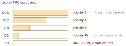
The elegance is that the display holds high priority for a tiny fraction of the time. Most cycles the CPU sees no interference, and the hard deadline is still met because whenever the display is genuinely at risk it wins absolutely. You get the CPU's average case and the display's worst case together. This is exactly what AXI's 4-bit AxQOS field carries.
Per-class virtual channels. All of the above assumes classes are not stuck behind each other. Priority means nothing if the urgent packet is physically trapped behind a best-effort one in a shared FIFO.
So the answer to "give the display latency guarantees without starving the CPU" is three mechanisms each doing one job. Separate VCs so classes cannot block each other, token buckets on CPU and GPU so the display's worst case is computable, and urgency escalation so the display takes priority only when it needs it.
06.Part 6, the AMBA family
ARM's AMBA is the dominant on-chip protocol family, and since Apple silicon is ARM-based it is the right family to know. It is a set of protocols at different price points, and knowing which to pick where is the actual skill.
6.1 VALID and READY, the foundation under all of it
Two blocks on one clock, one has data, the other must take it. Both must consent and both must know the other consented, within one cycle. So use two wires pointing opposite ways. The producer drives VALID, meaning the payload is good right now. The consumer drives READY, meaning it has somewhere to put a payload this cycle. A transfer occurs on any rising edge where both are high. That is the entire protocol.
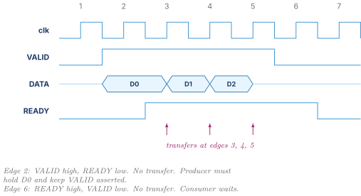
Three rules, each derivable rather than memorized.
Once VALID is asserted it stays asserted with the payload unchanged until a transfer occurs. Otherwise a producer could offer data and withdraw it next cycle, and a consumer that decided its READY a cycle earlier would latch garbage. The rule makes VALID a binding commitment.
VALID must never depend combinationally on READY. READY may depend on VALID, since consumers often mean "ready if there is something to take and I have a slot." If VALID also looked at READY in the same cycle you would have a combinational loop, which is not a circuit but an oscillator. The asymmetry keeps the loop open.
Neither side waits for the other before asserting. A producer withholding VALID until it sees READY, facing a consumer withholding READY until it sees VALID, is a two-party deadlock built from politeness.
Throughput is one transfer per cycle when both stay high, half that if the consumer accepts every other cycle. That stalling is backpressure and it propagates upstream naturally. A skid buffer is the standard fix when READY must be registered for timing, since registering it means the producer learns about a full consumer a cycle late and may send one extra beat. Registering a ready signal always requires a slack entry somewhere, and forgetting that is a common bug.
6.2 APB and AHB, the cheap one and the legacy one
APB is non-pipelined with no bursts and no outstanding transactions, two phases and a two-cycle minimum. SETUP drives PADDR, PWRITE, PWDATA and asserts PSEL with PENABLE low. ACCESS raises PENABLE until the slave asserts PREADY.
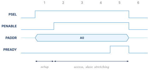
Peak throughput is one transfer per two cycles and it never improves. Why build something this weak? A configuration block might hold 200 registers software touches once at boot. Writing all 200 over APB at 100 MHz costs 400 cycles, four microseconds, once at power-on. Nobody notices. Wiring full AXI to each tiny register block costs hundreds of extra wires, a decoder, buffering, and a larger verification burden, to save two microseconds one time. APB is right whenever bandwidth genuinely does not matter, and recognising that case is a skill rather than a limitation.
AHB overlaps the address phase of one transfer with the data phase of the previous one.
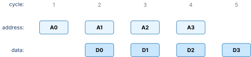
Sustained throughput is one per cycle when nothing stalls. It is still a shared bus with a central arbiter and a big mux collecting HRDATA, and its fatal limit is one outstanding transaction. A slave taking 20 cycles stalls the entire bus, every master on it, for those 20 cycles. As memory latency grew that became unacceptable. Legacy in new designs, common in existing IP.
6.3 AXI and its five channels
AXI is the workhorse, and its defining feature is five completely independent channels, each with its own VALID/READY pair, each free to stall without stalling the others.
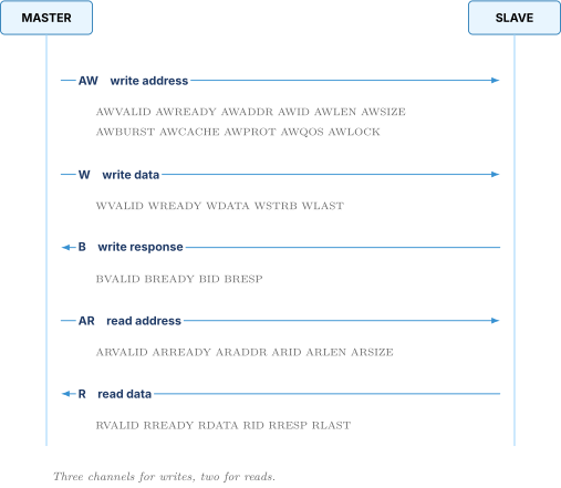
Why address and data are separate gets asked directly, so have several reasons.
They run at different rates. One address covers a whole burst, so a 16-beat burst is one AW beat and sixteen W beats, and sharing a channel would carry 40 bits of address alongside 128 bits of data on all 17, wasting the address wires on 16 of them.
It pipelines across transactions. The master pushes the address for transaction while data for streams, so neither waits on the other's slow path.
The two paths go through different fabric logic. The address path passes through decode and arbitration, deep combinational logic and often a critical path. The data path is a wide mux with almost no decode. Separating them lets the fabric add register stages to the address path without imposing them on the wide data path. Merged, the wide path would inherit the narrow path's latency.
Reads and writes proceed independently, so a long write burst cannot block a read from issuing. And backpressure is scoped, since a slave out of write buffer deasserts WREADY without stalling AR.
6.4 Outstanding transactions and the AXI ID
Outstanding means issued but not complete. A 64-byte read burst returns 100 cycles later. With one outstanding transaction the master gets 64 bytes per 100 cycles, 0.64 bytes per cycle, which at 2 GHz is 1.28 GB/s. Pitiful. With 16 outstanding it gets 1024 bytes per 100 cycles, 10.24 bytes per cycle, 20.5 GB/s. Sixteen times the bandwidth over the same wires.
Turned around by Little's law from 7.1, sustaining 32 bytes per cycle at 100-cycle latency with 64-byte transactions needs
That number sizes your tracking structures and MSHRs, and it is why a modern cache has dozens of miss-handling registers.
Now the ordering problem. With fifty in flight completing out of order, how does anyone know which data belongs to which request, and how do you keep the ordering software requires? The ID field, AWID and ARID outbound, BID and RID inbound, enforces exactly one rule. Transactions with the same ID must complete in issue order. Transactions with different IDs may complete in any order.
That sentence is a dial between ordering and parallelism. Three reads issued back to back.
| Issue order | ID | Target | Raw latency |
|---|---|---|---|
| 1st, address X | 0 | DRAM | 200 cycles |
| 2nd, address Y | 1 | on-chip SRAM | 10 cycles |
| 3rd, address Z | 0 | on-chip SRAM | 10 cycles |
Y has a different ID so its data may return first, which is the win, a fast access not stuck behind a slow one. Z shares ID 0 with X, so even though Z's data is ready at cycle 10 it is held until X returns at cycle 200.
| Completion order | Legal | Why |
|---|---|---|
| X, Y, Z | yes | in order, always legal |
| Y, X, Z | yes | Y is a different ID, X before Z preserved |
| X, Z, Y | yes | X before Z preserved, Y free |
| Z, X, Y | no | Z returned before X and they share ID 0 |
One ID everywhere gives strict ordering free at the cost of serializing behind the slowest access. Unique IDs give maximum parallelism at the cost of reassembling order yourself in a reorder buffer, which is a CAM lookup on the returning ID per Arbiters FIFOs and CAMs. Real masters land in between, using the ID to encode the destination region or internal requester so things that must stay ordered naturally share an ID.
One fabric detail. An interconnect merging masters appends bits to the incoming ID to record the source, so a fabric joining 4 masters with 4-bit IDs presents 6-bit IDs to the slave. If the slave supports fewer ID bits than the fabric produces, the fabric must serialize, silently destroying the parallelism you designed for.
6.5 Bursts, and the wrapping burst worked
AxLEN is the beat count, AxSIZE the bytes per beat, AxBURST the type. FIXED holds the address constant, which is what you want writing repeatedly to a hardware FIFO port. INCR increments by the transfer size, ordinary memory. WRAP increments but wraps to a lower boundary, and it exists for exactly one reason.
A CPU misses on a load. The line is 64 bytes, the link delivers 16 bytes per beat, so the line takes 4 beats. The CPU does not want the whole line, it wants the bytes it asked for and is stalled until it gets them. That is the critical word.
Take a miss on 0x1068. The line runs 0x1040 to 0x107F with beats at 0x1040, 0x1050, 0x1060, 0x1070, and the critical word sits in the beat at 0x1060, the third in address order. Issue a WRAP burst with ARADDR = 0x1060, ARLEN = 3 for four beats, ARSIZE = 4 for 16 bytes. The wrap boundary is bytes, so the address wraps at the aligned base 0x1040.
| Beat | Address | Covers | What happens |
|---|---|---|---|
| 1 | 0x1060 | 0x1060 to 0x106F | critical word, CPU unblocks here |
| 2 | 0x1070 | 0x1070 to 0x107F | |
| 3 | 0x1040 | 0x1040 to 0x104F | address wrapped |
| 4 | 0x1050 | 0x1050 to 0x105F | line complete |
The CPU restarts after beat 1 instead of beat 3, saving 8 cycles here at 4 cycles per beat and about 1.5 beats per miss averaged over random critical-word positions. Multiply by hundreds of millions of misses.
Two further benefits. The cache controller needs no reassembly logic, because every beat carries an address saying where in the line to write, and the line is complete after exactly AxLEN+1 beats regardless of start. And it stays one transaction, consuming one ID slot and one arbitration. The alternative is two INCR bursts, doubling address overhead and losing atomicity.
Other fields fill out the picture. WSTRB is one byte-enable per data byte, letting a single-byte store use a wide bus without read-modify-write. WLAST and RLAST mark the final beat so the receiver need not count. AxCACHE says whether a transaction is cacheable, bufferable, and allocating. AxPROT carries privilege and secure-world information. AxQOS is the 4-bit priority from 5.2. AxLOCK marks exclusive accesses implementing load-linked and store-conditional, connecting to Virtual Memory and Memory Ordering. AXI4-Lite drops bursts and keeps single beats with the full channel structure, a good register-block interface. AXI4-Stream drops addresses entirely, which is what a DMA pipe or video stream wants.
6.6 ACE, coherence over AXI
ACE, AXI Coherency Extensions, adds three inbound channels so a master can be snooped. AC carries the snoop address from interconnect to master, CR the snoop response back, CD the snoop data back.
The consequence is architectural. An ACE master is no longer purely a requester. It has an inbound port other agents drive, so it must service snoops while its own requests are outstanding, which is precisely the request-versus-snoop dependency 4.3 said needs separate virtual channels. Building an ACE master without separating those classes is a deadlock waiting for the right traffic.
ACE carries five line states mapping onto the MOESI family from Cache Coherence Protocols. UniqueDirty, UniqueClean, SharedDirty, SharedClean, Invalid. Unique means no other cache holds it so you may write without asking, Dirty means you owe memory a writeback.
ACE also defines shareability domains, Non-shareable, Inner, Outer, System, and a snoop goes only to masters inside the named domain. Four CPUs sharing an Inner domain means an Inner Shareable transaction snoops those three siblings and never disturbs the GPU or the other cluster. Getting domains wrong either breaks coherence or wastes enormous snoop bandwidth.
ACE-Lite serves masters that must see coherent data but have no cache to be snooped. A DMA engine reading a buffer the CPU just wrote issues an ACE-Lite ReadOnce, which snoops the CPU caches and pulls the dirty line directly. Without it, software must clean the CPU cache to memory first, costing thousands of cycles per buffer and much driver complexity.
6.7 CHI, the packet-based successor
CHI, Coherent Hub Interface, replaces ACE's signal-based structure with a packet-based one over layered protocol, link, and physical layers.
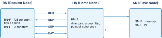
A request node starts transactions, RN-F fully coherent with a snoopable cache and RN-I an IO-coherent requester without one. The home node is the point of coherency for an address range, owning the directory, deciding which snoops are needed, issuing them, collecting responses, and either forwarding data from another cache or fetching from a slave node. A slave node is a memory controller or IO endpoint with no coherence responsibility. Every coherent request goes to the home node, which is the fundamental difference from ACE.
Why packets scale better is worth saying. Signal-based ACE has a fixed wire bundle per channel with ordering rules bound up in that structure, fine when the interconnect is a small crossbar. A packet carries its own destination, message class, and transaction identifier, so it traverses an arbitrary mesh with many hops without the protocol caring about topology, and layering lets the physical layer widen or clock-cross without touching the protocol. CHI defines exactly the four classes from 4.3, REQ, RSP, SNP, DAT, each on its own virtual channel, so deadlock freedom is built into the protocol rather than bolted on by the integrator.
The scaling argument with numbers. Eight coherent clusters, each generating a coherent miss per 10 cycles at 3 GHz, so 0.3 billion requests per second each and 2.4 billion total. ACE broadcast snoops the other 7 per request, giving billion snoops per second. A CHI home node whose snoop filter knows only 1.2 caches on average hold a line sends billion. Nearly a 6x reduction, and the gap grows with cluster count because broadcast is per request while filtered snooping is roughly constant. So broadcast is fine to roughly 4 to 8 coherent masters, and beyond that snoop bandwidth becomes the bottleneck and you need a directory.
6.8 The family in one table
| APB | AHB | AXI | ACE | CHI | |
|---|---|---|---|---|---|
| Structure | 2-phase | pipelined bus | 5 channels | AXI + 3 snoop | packet, layered |
| Outstanding | 1 | 1 | many | many | many |
| Out of order | no | no | yes, by ID | yes | yes |
| Bursts | no | yes | yes, incl. WRAP | yes | yes |
| Coherent | no | no | no | yes, broadcast | yes, directory |
| Scales to | a few registers | a few masters | tens of masters | 4 to 8 coherent | many clusters |
| Use for | config registers | legacy IP | the main fabric | small coherent SoC | large coherent SoC |
07.Part 7, flow control, buffering, and bridges
7.1 Little's law, and how big the buffer must be
Little's law says that for any stable system the average number of items inside equals the arrival rate times the average time each spends inside.
It holds for queues, pipelines, and coffee shops, and needs no assumption about the arrival distribution. Here it answers both "how much buffering" and "how many outstanding transactions" the same way.
A link delivers 16 bytes per cycle. The credit round trip is 20 cycles, 10 for a flit to reach the receiver and 10 for the acknowledgement to come back and take effect. To never stall, the sender must be allowed 20 cycles of data in flight before the first credit returns.
Build fewer and trace it.
| Receiver buffer | Cycles sending | Cycles stalled | Duty cycle | Achieved bandwidth |
|---|---|---|---|---|
| 4 flits | 4 | 16 | 20 percent | 3.2 B/cycle |
| 8 flits | 8 | 12 | 40 percent | 6.4 B/cycle |
| 16 flits | 16 | 4 | 80 percent | 12.8 B/cycle |
| 20 flits | 20 | 0 | 100 percent | 16.0 B/cycle |
| 32 flits | 20 | 0 | 100 percent | 16.0 B/cycle |
Two lessons. Under-buffering fails in exact proportion, so an 8-flit buffer on a 20-cycle link delivers 40 percent of the link you paid to build. And over-buffering buys literally nothing, as the last row shows, while adding latency under congestion because packets sit in deeper queues. There is a right answer and it is the bandwidth-delay product.
The same law sizes outstanding transactions. Sustaining 16 bytes per cycle from a memory system with 100-cycle latency using 64-byte fills needs concurrent fills, so twenty-five MSHRs. That is why the miss-handling structures in Cache Organization and Prefetching are as large as they are, and it is worth deriving rather than recalling.
7.2 Credit-based flow control
The sender keeps a counter of the receiver's free slots. Sending decrements it, receiving a credit increments it, and the sender never sends at zero, so the receiver never overflows and no flit is ever dropped.
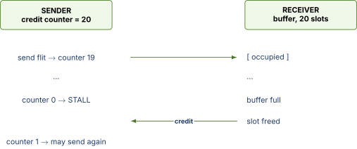
Plain VALID/READY backpressure is fine when the ends are adjacent. Over a link with 10 cycles of flight each way, READY reports a condition true 10 cycles ago and the sender has launched 10 more flits meanwhile, so you need 10 slots of slack anyway. Credit-based flow control is that slack made explicit and counted, which is why it is correct over any non-local link. On/off, sometimes Xon/Xoff, sends stop above a high watermark and go below a low one, which is one bit rather than a counter but needs a full round trip of watermark headroom, making the buffer larger for the same performance.
One rule people get wrong. Credits must be per virtual channel, never pooled. A shared pool lets a saturated VC consume every credit and stall the others, reconstructing exactly the head-of-line blocking and class-mixing deadlock the VCs were introduced to prevent in 4.3. Shared credits silently undo the deadlock-freedom argument, and the failure appears only under a traffic pattern you did not simulate.
7.3 Protocol conversion and bridge deadlock
Real SoCs mix protocols and clock domains, so bridges are everywhere. AXI-to-APB for register blocks, AXI-to-AXI across clock domains, width converters, CHI-to-AXI at a memory controller. Every one is a place a designer can create a deadlock that no individual block contains.
The classic is two buses joined by a bidirectional bridge with a shared buffer pool.
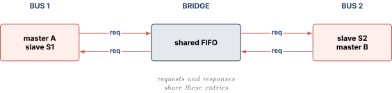
Master A targets slave S2 across the bridge, master B targets slave S1 the other way, and both directions fill with requests. S2 wants to send A's response back, but 2-to-1 is full of B's requests. S1 wants to send B's response, but 1-to-2 is full of A's. Neither drains, because draining needs the responses stuck behind the requests. That is the protocol cycle from 4.2, rebuilt by a bridge that pooled two message classes.
Four fixes, in the order a real design applies them. Never share buffering between requests and responses, separate FIFOs at minimum. Guarantee responses always drain, since a response terminates at a requester who already reserved the slot, so a dedicated response path is always ultimately consumable and the graph stays acyclic. Bound outstanding transactions per bridge so it can always accept a new request, tracking at most transactions with response slots. And restrict the topology by design rule, which is the most common real answer and worth saying because it shows you have shipped something. Many SoCs simply forbid cyclic master-slave relationships across bridges, enforced in the address map and checked at integration rather than in RTL, removing an entire bug class for zero gates.
Two other bridge hazards are frequent enough to name. Write channel ordering, since AXI lets AW and W be issued independently and a bridge coupling them wrongly deadlocks when a master pushes several addresses before their data. AXI3 permitted write-data interleaving tagged with a WID and it was a rich source of bugs, and AXI4 removed WID and requires write data in address order. And clock domain crossing, since a bridge must not turn the slow side's backpressure into a combinational path. The correct structure is an async FIFO per channel with credits sized by synchronizer latency, per Clocking Reset and Domain Crossing. A bridge is one of the few places with both a protocol deadlock risk and a metastability risk on the same wires.
08.Part 9, check yourself
Answer out loud, in full sentences, as if an interviewer asked. If you cannot, reread the section named.
- Define bisection bandwidth from scratch and explain why it caps aggregate throughput no matter how good the routing is. (1.2)
- Compare bus, crossbar, ring, and mesh at and at . State which ranking changes between them and why. (2.1 to 2.5)
- A colleague says a mesh is cheaper than a crossbar. Is that true in gates? What is the mesh actually buying? (2.2, 2.4)
- Compute the latency of a 5-flit packet over 4 hops under store-and-forward and under wormhole, and say what wormhole costs in exchange. (3.2, 3.3)
- Name the four conditions for deadlock, say which one on-chip networks break, and say why they cannot break the others. (4.1)
- Describe the request-response deadlock cycle precisely, including why it happens on a crossbar with no topology at all. (4.2)
- Explain exactly why virtual channels break that cycle. The load-bearing step is that responses are always consumable, so say why that is true. (4.3)
- Prove that XY dimension-ordered routing is deadlock free using the channel dependency graph. (4.4)
- What does an escape virtual channel do, and why does adding one restore the proof for an adaptive network? (4.5)
- A display controller and a CPU share a fabric. State what each actually needs, then design a QoS scheme that meets the deadline without starving the CPU. (5.1, 5.2)
- State the three VALID/READY rules and derive why VALID must not depend combinationally on READY. (6.1)
- Give four independent reasons AXI separates the address and data channels. (6.3)
- A master issues reads to X with ID 0, Y with ID 1, and Z with ID 0, in that order. Which completion orders are legal and which is not? (6.4)
- Walk through a 4-beat WRAP burst for a miss on
0x1068with a 64-byte line, listing beat addresses, and give three benefits over two INCR bursts. (6.5) - When would you move from ACE to CHI? Support it with a snoop bandwidth calculation. (6.6, 6.7)
- Size the buffering for a 16 byte per cycle link with a 20 cycle credit round trip, say what happens at half that and at double it, and say why credits must be per virtual channel. (7.1, 7.2)
- Describe a bridge deadlock between two buses and give four ways to prevent it, ordered by what a real design does first. (7.3)
09.Part 10, related notes
- Cache Coherence Protocols for the MESI and MOESI states ACE and CHI carry, and the snoop filter behind the CHI home node
- Arbiters FIFOs and CAMs for the arbiters inside every router, the FIFOs behind every credit counter, and the CAM that reorders AXI responses by ID
- Digital Logic and Timing for why long global bus wires are slow, and for the skew consequences of gating a router's clock
- Cache Organization and Prefetching for MSHRs, the outstanding-transaction budget of 6.4 seen from the cache side
- Clocking Reset and Domain Crossing for the async FIFO inside every clock-crossing bridge
- SoC Integration and Interfaces for address maps and the design-rule fix for bridge deadlock
- DFT and Silicon Debug for the trace and trigger infrastructure that finds a fabric hang after tapeout
- I/O Architecture for PCIe, DMA, IOMMU, and CXL, the off-chip analogue of everything here
- DRAM and Memory Controllers for the memory-side scheduling at the far end of the fabric