Advanced Cache Topics
September 13, 202625 min readadvanced
The basic cache organizations of Chapter 37 and the performance analysis of Chapter 38 cover what real designs are. They do not cover what real designs do beyond those basics. This chapter surveys the…
The basic cache organizations of Chapter 37 and the performance analysis of Chapter 38 cover what real designs are. They do not cover what real designs do beyond those basics. This chapter surveys the techniques that high- performance processors layer on top of the foundation. Each technique addresses a specific shortcoming. Skewed associativity attacks conflict misses without the area cost of higher associativity. Way prediction attacks the energy of multi-way lookups. Line buffers attack the lookup cost of repeated accesses to the same line. Sectored organizations attack tag-storage overhead. Compression attacks the size constraint. Bypass attacks pollution. Dead-block prediction attacks the wasted-storage problem. Each is a refinement, not a revolution, but together they account for a large fraction of the AMAT improvement that modern caches deliver over their textbook ancestors.
The chapter does not aspire to be exhaustive. Cache research has produced a vast literature over four decades, and any complete survey would fill its own book. The selection here covers the techniques that have made it into commercial processors and that a graduate-level reader should recognize when encountering an architectural disclosure or a research paper.
01.Skewed-Associative Caches
The set-associative caches of Chapter 37 use the same index bits to select sets in every way. This is the source of correlated conflicts. Two addresses that happen to share the same index field collide in every way of the set. Skewed associativity, introduced by Seznec [1], breaks the correlation by giving each way its own index function.
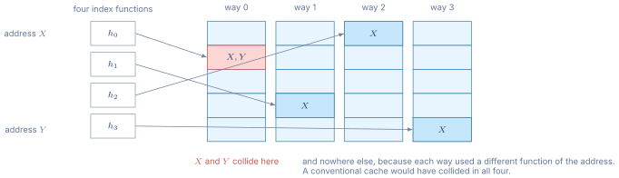
Figure 1 shows the correlation being broken.
The Mechanism
A 4-way skewed-associative cache has four sets selected per access, one per way, computed by four different hash functions of the address. The functions are chosen so that two addresses that collide in one way are unlikely to collide in another. A simple choice is
\begin{align*} \text{set}_0(A) &= A_{[5:0]} \quad \text{(low 6 bits, ignoring offset)} \\ \text{set}_1(A) &= A_{[5:0]} \oplus A_{[11:6]} \\ \text{set}_2(A) &= A_{[5:0]} \oplus A_{[17:12]} \\ \text{set}_3(A) &= A_{[5:0]} \oplus A_{[23:18]} \end{align*}
where is bitwise XOR. Each way reads a different set, and the four tag comparisons happen in parallel as in a normal 4-way design. A hit in any of the four ways returns the data.
Why It Helps
Consider two addresses and that share the same low-6-bit index. In a standard 4-way cache they collide in every way. In a skewed cache they collide only in way 0. In ways 1, 2, and 3 their indices depend on different higher-order bits and are unlikely to match. The chance that a single line of and a single line of collide in all four ways drops by roughly a factor of for the simple XOR-hash example.
Empirically, skewed associativity gives miss rates close to a cache with double the conventional associativity. A 4-way skewed cache performs like an 8-way conventional cache for many workloads, with the area cost of the 4-way (no additional tag comparators or data ports).
The Cost
The cost is the hash computation and a more complex replacement policy. With four different index functions, a single line can live in only one place per way, so a true LRU ordering across the set is not well-defined (the four candidates per access are four different lines, not the same four). Practical implementations use NRU or RRIP-style policies that do not require strict ordering.
Skewed associativity appears in some commercial designs (Compaq Alpha 21464, some IBM POWER variants) but is less common than straight high-associativity layouts. The reason is that conventional 8-way caches have become cheap enough at modern process nodes that the area saving from a 4-way skewed design is not worth the complexity. Skewed associativity is more common today in TLBs and in branch predictors, where high associativity is genuinely costly.
02.Way Prediction
A standard 8-way set-associative cache reads all 8 data arrays in parallel with the tag comparison, then selects the matching way’s data through a multiplexer. This is fast but burns energy on the 7 ways that did not match. Way prediction tries to read only the predicted way’s data array, saving energy when the prediction is correct.
The Mechanism
A small table indexed by the program counter or the load PC stores, for each recently-seen load, which way the load most recently hit. On a new access, the load PC indexes the table and produces a predicted way. The cache reads only that way’s data array and performs the tag comparison in parallel.
If the prediction is correct, the data is ready as soon as the tag comparison confirms the hit. Latency is unchanged from the standard parallel lookup. Energy drops by roughly a factor of 8 (only one of the eight data arrays is read).
If the prediction is wrong, the cache must perform a second-cycle lookup of the remaining ways. The miss-prediction penalty is typically one cycle.
Practical Use
Way prediction is heavily used in low-power and mobile designs. The Cortex-A53, Cortex-A55, and many SiFive RISC-V cores use way prediction in their L1 data caches. Misprediction rates are typically 5 to 10 percent, so the energy savings amortize cleanly over the small per-miss penalty.
High-performance cores like Cortex-A77 or Intel Golden Cove rarely use way prediction because their energy budgets are different and the latency cost of a miss matters more. In a desktop or server core, the priority is hit time. In a phone core, the priority is energy per access. Way prediction is a clear win in the latter regime and an uncertain one in the former.
03.Line Buffers and Critical-Word-First
A typical 64-byte cache line takes multiple bus cycles to transit the on-chip interconnect. A 32-byte/cycle bus delivers a 64-byte line in 2 cycles. A 16-byte/cycle bus takes 4. During the transit, the cache controller could either (a) wait for the full line before beginning to forward data to the processor, or (b) start forwarding the requested word as soon as it arrives.
Critical-Word-First
Modern designs almost universally use critical-word-first delivery. The memory controller is informed which word within the line was the actual target of the load instruction. It arranges the line transfer so that word arrives first, wrapping around through the rest of the line afterward. The processor’s load instruction can complete as soon as the critical word arrives, even though the remaining bytes of the line are still in transit.
For a 64-byte line on a 16-byte bus, critical-word-first reduces the effective miss latency by up to 3 cycles per miss. The full line still arrives in 4 cycles, but the requested word arrives in 1.
Line Buffers
A line buffer is a small SRAM that holds the most recently fetched cache line. When a load arrives, the cache checks the line buffer first. If the load’s target address is within the buffered line, the cache returns the data directly from the buffer, bypassing the tag comparison.
The benefit is twofold. First, repeated accesses to the same line (very common in sequential code) avoid the energy and latency of the full cache lookup. Second, on a miss, the missing line lands in the line buffer first, and subsequent accesses to that line hit the buffer while the cache controller is still installing the line in the SRAM array. This effectively makes the missing line "warm" before it is fully installed.
Some designs use multiple line buffers, one per way of recent access, blurring the boundary between line buffers and a small L0 cache.
04.Sectored Caches
In a standard cache, the line is the unit of both tag storage and data transfer. A 64-byte line has one tag and one valid bit. A sectored cache allows the line to be larger than the transfer unit, with one tag covering multiple sub-blocks (sectors), each with its own valid bit.
The Tradeoff
Sectored organizations reduce tag storage. A cache with 256-byte lines and 4 sectors of 64 bytes each uses one tag per 256 bytes instead of four tags for the same data, cutting tag storage by 4x. For large caches with long lines, the savings can be substantial.
The cost is that a sectored line can be partially valid. If the program accesses only one sector of the line and never the others, the cache wastes capacity on the unused sectors (since they share the line slot). Miss handling also becomes more complex: a miss on an invalid sector of a valid line requires a fetch of just that sector, not the full line.
When Sectoring Helps
Sectored caches shine when (a) tag storage is a bottleneck (very large LLCs with short lines), or (b) the program has very strong spatial locality but at a granularity larger than the natural line size. An L3 with 64-byte sectors inside 256-byte lines pays one tag per 256 bytes but fetches only 64 bytes when only one sector is referenced. The Intel Pentium 4 trace cache used a sectored organization for its trace storage, and some recent ARM designs use sectored organizations in their L3.
Sectoring is uncommon in L1 caches, where line size and transfer size are typically equal and tag storage is not a binding constraint.
05.Compressed Caches
A compressed cache stores lines in a compressed encoding, packing more lines into the same SRAM area. The motivation is straightforward. Many cache lines contain substantial redundancy: zero runs, repeated values, narrow integers. If the cache can compress these lines, more of the program’s working set fits, and the miss rate drops.
Compression Schemes
The compression must be very fast to be useful, because cache hit time is on the critical path of every memory access. Schemes that take dozens of cycles to compress or decompress are unworkable.
Base-Delta-Immediate (BDI) compression [2] is the most-cited scheme. It identifies cache lines whose values can be encoded as a base value plus small per-value deltas. A 64-byte line of 16 four-byte integers that all fall within 256 of each other can be encoded as one 4-byte base plus 16 one-byte deltas, a total of 20 bytes instead of 64. Compression and decompression are single-cycle arithmetic operations.
Other schemes target specific patterns. Frequent-Pattern Compression (FPC) [3] identifies common patterns like all-zeros, sign-extended-small-integer, and zero-extended-byte, and encodes each with a fixed prefix. Both BDI and FPC achieve roughly 1.5 to 2x compression on typical workloads.
The Practical Story
Compressed caches are an active research area but have not made substantial commercial inroads. The reason is that the area saved by compression rarely justifies the design complexity. SRAM is expensive, but managing variable-size lines, handling decompression on every read, and coping with compression-rate variability across workloads add enough engineering cost that the simpler approach of just making the cache bigger usually wins.
The exception is the LLC of some recent designs, where compression gives a real capacity boost without affecting hot-path latency. The IBM POWER10 LLC, for example, uses a compression scheme similar to BDI.
06.Cache Bypass
Some memory accesses do not benefit from caching. A streaming workload that reads a 100-MB array exactly once has no temporal locality and only modest spatial locality. Bringing each cache line into the L1 displaces useful data and provides no future-access benefit.
Cache bypass lets such accesses skip the cache and go directly to the next level (or to memory). The processor avoids polluting the cache, and the streaming data flows through without disturbing resident working sets.
Software-Directed Bypass
The most common form is software-directed. The ISA provides non-temporal load and store instructions that the program uses to mark streaming accesses. Examples include x86’s movntdq family, ARM’s non-temporal load and store instructions, and the RISC-V Zihintntl extension’s non-temporal locality hints.
The compiler inserts non-temporal hints based on programmer annotations (#pragma stream, __builtin_expect-style hints) or through auto-vectorization analysis. The runtime cost is zero (the hint just modifies the load’s behavior), and the benefit is substantial when the access pattern is known to be streaming.
Hardware-Directed Bypass
Some designs add hardware bypass triggers. A pattern detector observes the access stream and, when it identifies a long sequential or strided pattern that exceeds some threshold, switches subsequent accesses to bypass mode. The pattern detector is closely related to the stream prefetcher, covered in the next chapter.
Hardware bypass is rare in commercial designs because mispredictions are costly (the bypassed line might have been re-referenced) and the policy is hard to tune across workloads. Software-directed bypass dominates in practice.
07.Dead-Block Predictors
A cache line is dead if no future access in the program touches it before it is evicted. By definition, every line eventually becomes dead. The question is when.
A dead-block predictor tries to identify dead lines early and evict them, freeing space for live lines. The predictor’s output is a per-line confidence value that the line is no longer useful. When the confidence crosses a threshold, the line is moved to a victim cache or simply evicted.
Why Prediction Works
In most workloads, a few specific access patterns indicate that a line is unlikely to be reused. A line that has just been accessed for the third or fourth time, with no intervening writes, often goes dead soon after (the program has finished its loop over that data). A line that has been touched once and not again for many cycles is likely dead (no temporal locality on that address).
Lai et al. [4] proposed using the trace of PCs that accessed a line as the prediction input. The same sequence of PCs touching a line typically produces the same death time across instances of that line. Subsequent work refined the predictors to use simpler features (counter of accesses, time since last access) that are easier to track in hardware.
Practical Use
Dead-block prediction is used in some commercial LLCs, where its benefit is largest. A 32-MB L3 with 30 percent dead lines at any time effectively wastes 10 MB of capacity. Identifying those lines early and reusing the space provides a real hit-rate improvement.
The technique is rarely used in L1, where the dead-block fraction is smaller (because L1 lines turn over quickly anyway) and the prediction logic would add to the critical path.
08.Non-Blocking Caches and MSHRs
A blocking cache stalls every subsequent access while a miss is being handled. A modern processor would lose enormous throughput under such a policy. A non-blocking cache continues to serve hits while one or more misses are being fetched, and can also handle multiple outstanding misses simultaneously.
Miss-Status Holding Registers
The mechanism is the miss-status holding register (MSHR), introduced by Kroft [5]. An MSHR records one outstanding miss: the missing address, the register that will receive the data, and any other state needed to complete the access when the line arrives.
A cache with MSHRs can support outstanding misses simultaneously. When a miss occurs, the cache allocates an MSHR, issues the fetch to the level below, and continues serving hits and new misses (which allocate additional MSHRs if available). When the missing line arrives, the cache fills the line, deallocates the MSHR, and signals the waiting register to receive the data.
Modern L1 caches have 8 to 16 MSHRs. L2 caches typically have 24 to 32. L3 caches and memory controllers have hundreds.
Memory-Level Parallelism
The MSHR count is one of the binding constraints on memory-level parallelism. A processor that can dispatch 30 independent loads but has only 8 MSHRs in L1 cannot keep more than 8 misses outstanding. The DRAM channel that could absorb 30 simultaneous requests goes underutilized.
Out-of-order execution (Part V) raises the demand for MSHRs. A large reorder buffer can hold dozens of in-flight loads, and each load that misses L1 needs an MSHR until it completes. Modern high-performance designs scale MSHRs aggressively for this reason.
09.Cache Coherence Preview
This chapter has treated the cache as a single-core mechanism. Multi-core processors raise an additional set of design problems because two cores can have copies of the same line in their L1 caches simultaneously. Keeping those copies consistent is the problem of cache coherence, whose full treatment lies beyond this book.
The relevance here is that several techniques covered above interact with coherence. Inclusive caches simplify coherence (the LLC serves as the directory). Exclusive caches complicate coherence (every level must be snooped). Dead-block prediction must respect coherence (a line that another core might soon request cannot be evicted casually). Cache bypass must coordinate with the coherence protocol so that the bypassed write is not lost.
The takeaway here is that no cache design choice is local. Every choice cascades into the coherence protocol, the memory consistency model, and the inter- core communication patterns.
10.Survey of Commercial Designs
To ground the chapter in real designs, the following list cites public disclosures of cache features in recent processors. All information comes from vendor architecture references, Hot Chips disclosures, or peer-reviewed papers. No proprietary microarchitecture details are included.
Table 1. Public disclosures of cache techniques in recent high-performance processors. Information drawn from vendor architecture references and Hot Chips presentations.
| Processor | Disclosed cache features |
|---|---|
| ARM Cortex-A510 | Way-prediction L1, victim buffer between L1 and L2 |
| ARM Cortex-A710 | 8-way L1, replacement based on re-reference prediction |
| ARM Neoverse N2 | NINE L1/L2/L3, MSHR depth 24+ |
| Intel Golden Cove | NINE L1/L2/L3, dead-block-driven L3 partitioning |
| AMD Zen 4 | NINE L1/L2, exclusive-like L2/L3 movement, RRIP-style L3 |
| SiFive U74 | Way-prediction L1, simple direct-mapped victim buffer |
| IBM POWER10 | Compressed L3 lines, sectored L3 |
The pattern that emerges is that mobile designs (Cortex-A510, SiFive U74) lean on way prediction and small victim buffers for energy efficiency, while server designs (Neoverse N2, Golden Cove, Zen 4) lean on large MSHRs, advanced replacement, and inclusion- policy flexibility for throughput. Compression appears at the L3 in a few designs but is not yet mainstream.
11.When to Use Which Technique
A graduate student approaching cache design for the first time may ask: which of the above techniques should I deploy? The honest answer is "it depends on the binding constraint." A summary by constraint:
-
Conflict misses are the bottleneck. Add associativity or use skewed associativity. Skewed wins on area when associativity is already high.
-
Energy per access is the bottleneck. Add way prediction. Useful only when the workload concentrates accesses in a small subset of ways.
-
Tag storage is the bottleneck. Use sectored organization. Most useful at the LLC.
-
Cache capacity is the bottleneck and the workload is compressible. Use compression. Active research, not yet mainstream.
-
Pollution from streaming accesses is the bottleneck. Add software-directed bypass via non-temporal load/store instructions.
-
Dead lines are wasting capacity. Add a dead-block predictor. Most useful at the LLC.
-
Memory-level parallelism is the bottleneck. Increase MSHRs and make the cache non-blocking. Every modern design does this.
The bottleneck depends on the workload, the cache level, and the process technology. A well-tuned cache hierarchy chooses different techniques at each level. The L1 emphasizes hit time and energy. The L2 emphasizes throughput. The L3 emphasizes capacity and coherence-protocol behavior. No single technique fits every level.
12.Looking Ahead
The next chapter develops prefetching, which attacks the same miss-penalty term in AMAT through a complementary mechanism. Rather than improving the cache structure, prefetching predicts upcoming accesses and fetches the data before the program asks for it. The chapter covers hardware prefetchers (stride, stream, GHB, SPP, Bingo, IPCP), software prefetchers (__builtin_prefetch), runahead execution, and dependency-graph-based prefetching for pointer-chasing workloads.
13.Worked Examples
14.Exercises
References
- [1]Seznec, Andr\'e (1993). “A Case for Two-Way Skewed-Associative Caches.” In Proceedings of the 20th International Symposium on Computer Architecture (ISCA), pp. 169--178. doi:10.1145/165123.165152
- [2]Pekhimenko, Gennady and Seshadri, Vivek and Mutlu, Onur and Gibbons, Phillip B. and Kozuch, Michael A. and Mowry, Todd C. (2012). “Base-Delta-Immediate Compression: Practical Data Compression for On-Chip Caches.” In Proceedings of the 21st International Conference on Parallel Architectures and Compilation Techniques (PACT), pp. 377--388. doi:10.1145/2370816.2370870
- [3]Alameldeen, Alaa R. and Wood, David A. (2004). “Adaptive Cache Compression for High-Performance Processors.” In Proceedings of the 31st International Symposium on Computer Architecture (ISCA), pp. 212--223. doi:10.1109/ISCA.2004.1310776
- [4]Lai, An-Chow and Fide, Cem and Falsafi, Babak (2001). “Dead-Block Prediction and Dead-Block Correlating Prefetchers.” In Proceedings of the 28th International Symposium on Computer Architecture (ISCA), pp. 144--154. doi:10.1145/379240.379259
- [5]Kroft, David (1981). “Lockup-Free Instruction Fetch/Prefetch Cache Organization.” In Proceedings of the 8th International Symposium on Computer Architecture (ISCA), pp. 81--87. doi:10.1145/285930.285979