Number Systems and Encodings
September 8, 202648 min readbeginner
Every piece of information inside a digital computer is a pattern of bits. The hardware itself knows nothing about integers, characters, images, or audio. It only knows whether each wire is at the high voltage…
Every piece of information inside a digital computer is a pattern of bits. The hardware itself knows nothing about integers, characters, images, or audio. It only knows whether each wire is at the high voltage or the low voltage. The mapping from bit patterns to the quantities we care about is a deliberate engineering choice, made once and then frozen into the instruction set. This chapter is about that choice. It develops the standard encodings the rest of the book takes for granted, from binary and hexadecimal through two’s complement signed integers to the modern Unicode text formats. Every architecture chapter that follows assumes these encodings without further explanation.
01.Why Encoding Matters
A digital circuit holds information as voltage levels on wires. A typical 2026-era logic gate runs on a supply of around 0.8 to 1.1 volts, with one of those two extremes representing the bit value and the other representing . The choice of which voltage is the is arbitrary at the circuit level. The hardware designer picks a convention, and every downstream layer of the system uses the same convention.
That bit, on its own, says nothing. A wire holding a is just a wire at the high voltage. The same bit could mean part of an integer, part of a memory address, part of a pixel color, the arming bit of a control register, or one of the eight bits that together encode the letter A. The interpretation lives in the surrounding hardware and software. A 32-bit register holding the pattern 0x41414141 carries the same charge whether software interprets it as the integer 1,094,795,585, as the four-character string "AAAA", or as the floating-point value approximately . The bits are the same. The meaning depends on the encoding.
Engineering practice therefore separates two questions. The first is what bit patterns the hardware can store and manipulate efficiently. The second is what meanings we assign to those patterns. Hardware optimizes the first question. Encoding standards answer the second. This chapter develops the encodings that the rest of the book uses without further introduction. Integer arithmetic in Chapter 7 assumes two’s complement. Floating-point arithmetic in Chapter 8 assumes IEEE 754. String handling across operating systems assumes UTF-8. Memory layout assumes a specific endianness. These choices are not minor. A processor that encoded signed integers differently would not be able to run software written for any modern operating system. Encoding is part of the architecture.
02.Positional Number Systems
The positional idea
The way we write the decimal number 2026 is a concise statement about powers of ten. Reading from the right, the digits weight the powers , , , and . The number itself decomposes as
Each digit position carries a fixed weight. The leftmost digit has the largest weight, the rightmost the smallest. This is the positional convention. It generalizes immediately to any base.
Let be a positive integer greater than or equal to 2, called the radix or base. A nonnegative integer written in base with digits , where each lies in the range to , equals
Equation the equation above is the whole engine of every number system in this chapter. The choice of changes which digits appear and how many positions a given quantity needs, but the underlying arithmetic of weighted digit positions is identical. The convention of writing the most significant digit on the left is also identical. Only the radix changes.
Binary, the radix of digital hardware
Set and only two digit values remain, and . These are the values a wire can take in a digital circuit. Binary is the natural language of hardware because the underlying primitive, the transistor, naturally distinguishes two states. Binary numbers therefore appear everywhere inside a computer. A 32-bit register stores a binary integer with up to 32 binary digits. A memory address is a binary integer. An instruction opcode is a binary pattern. The arithmetic that the ALU performs is binary arithmetic.
The vocabulary of binary quantities is part of the trade. A single binary digit is a bit. Four bits make a nibble, useful because four bits map cleanly to one hexadecimal digit. Eight bits make a byte, the smallest unit that essentially every modern processor can address directly. Beyond the byte, the groupings depend on the architecture. RISC-V and ARM AArch64 tie the names to fixed widths rather than to the register size, so a half-word is two bytes, a word is four bytes, and a double-word is eight bytes on RV32 and RV64 alike. The x86-64 family inherits the names of the 16-bit 8086, where a word is two bytes, a doubleword is four bytes, and a quadword is eight bytes. The terms are not universal across vendors, and any concrete code or specification fixes them explicitly.
The number of distinct values an -bit field can hold is . An 8-bit byte holds 256 distinct patterns. A 16-bit half-word holds 65,536 patterns. A 32-bit word holds about 4.29 billion patterns, and a 64-bit double-word holds about . These counts set fundamental limits on what a hardware structure of that width can encode. A 32-bit unsigned integer cannot represent values beyond . A 64-bit pointer cannot address more than distinct bytes, which is why current machines extend addressing only as the application demand and the physical memory technology jointly justify the area cost.
Octal and hexadecimal as human-friendly groupings
Writing a 32-bit value as a string of 32 binary digits is tedious and error-prone. The eye does not group long runs of 0s and 1s well. Two alternative bases sidestep the problem without leaving the binary world. Both are powers of two, which means digit-by-digit translation to and from binary is purely mechanical.
Octal uses radix 8. Each octal digit ranges from 0 to 7, and one octal digit encodes exactly three binary digits because . The 12-bit binary value groups from the right as , which reads as . Octal was common on early computers whose word widths were multiples of three, including the PDP-8 (12-bit words) and the PDP-10 (36-bit words). Modern usage is mostly limited to Unix file permission masks, where each three-bit octal digit corresponds to the read/write/execute triple for one user class.
Hexadecimal uses radix 16 and has dominated modern practice. Each hexadecimal digit ranges from 0 to 15 and encodes exactly four binary digits because . The digits 0 through 9 keep their decimal meaning, and the digits 10 through 15 are written using the letters A, B, C, D, E, and F. Lowercase a through f is accepted in every modern tool. The table below lists the sixteen hexadecimal digits next to their decimal and four-bit binary equivalents.
Table 1. Hexadecimal digits, their decimal values, and their four-bit binary equivalents.
| Hex | Decimal | Binary | Hex | Decimal | Binary |
|---|---|---|---|---|---|
| 0 | 0 | 0000 | 8 | 8 | 1000 |
| 1 | 1 | 0001 | 9 | 9 | 1001 |
| 2 | 2 | 0010 | A | 10 | 1010 |
| 3 | 3 | 0011 | B | 11 | 1011 |
| 4 | 4 | 0100 | C | 12 | 1100 |
| 5 | 5 | 0101 | D | 13 | 1101 |
| 6 | 6 | 0110 | E | 14 | 1110 |
| 7 | 7 | 0111 | F | 15 | 1111 |
A 32-bit value takes eight hexadecimal digits. The address is a 32-bit quantity with its highest bit set and the rest clear, which the reader can confirm in one glance. The same value in binary is , which takes considerably longer to scan and is easy to miscount. This convenience is the reason that essentially every register dump, memory dump, opcode listing, and address in this book uses hexadecimal.
Notation conventions
The same number written in different bases can be confused with a number written in decimal unless the base is made explicit. Three conventions are common in this book.
The mathematical convention is to write a subscript indicating the base, as in , , , and . This convention is unambiguous and is used in derivations.
The programming-language convention is to prefix the literal with a short marker. C, C++, Rust, Python, and Java all use 0b for binary, 0o (and historically a leading 0) for octal, and 0x for hexadecimal. Decimal needs no prefix. The literals 0b101101, 0o55, 0x2D, and 45 all denote the same value. This convention is used inside code listings and inline references to register values.
The hardware-description-language convention, used by Verilog and SystemVerilog, embeds the bit width as well as the base in the literal. The eight-bit hexadecimal value is written 8’h2D, the four-bit binary value is written 4’b0110, and the sixteen-bit decimal value is written 16’d45. This convention is used inside HDL code listings in later chapters.
Modern languages permit underscore separators inside numeric literals to aid reading. The 32-bit hexadecimal constant is sometimes written . The 16-bit binary constant is sometimes written . The underscores have no effect on the value, only on legibility.
03.Base Conversion
From any base to decimal
The equation above converts directly. Each digit, multiplied by the radix raised to the digit’s position index, contributes to the total. The sum across positions is the decimal value.
For binary , the digits from the right are at positions . The sum is
For hexadecimal , the digit A has value 10 and the digit B has value 11.
For a longer hexadecimal value such as , the weights grow with , which are , , , . The digits are , , , , reading from the right.
The arithmetic involves no special tricks. It is a careful application of the equation above.
From decimal to any base
The reverse direction uses repeated integer division by the target radix. The remainder at each step is the next digit, from least significant to most significant. The process stops when the quotient reaches zero.
To convert to binary, divide repeatedly by 2 and record the remainder.
Reading the remainders from the last division to the first gives the binary value . A quick verification by the equation above returns , which matches.
Converting to hexadecimal works the same way with radix 16. with remainder , and with remainder . The remainders are and , which encode as hex digits and . Reading from last to first gives , and indeed .
Direct conversion between binary, octal, and hex
Because and are powers of , conversion between binary and either of the two other bases sidesteps decimal entirely. Group the binary digits in threes (for octal) or fours (for hexadecimal), starting from the right. Each group translates directly to one digit of the target base.
The binary value groups in fours as written. Each group is a hex digit: , , , . The hex value is . In the other direction, the hex value expands as , , , , giving .
The same value can be regrouped in threes from the right to read in octal: , where a leading zero pads the leftmost group to a full three bits.
This direct conversion is why register dumps, memory dumps, and machine-code listings use hexadecimal in modern documentation. The reader who can read four binary digits at a glance reads any 32-bit value as a string of eight hex digits, then translates back to bit positions only where the bit-level structure matters.
04.Unsigned Integer Arithmetic
Binary addition
Adding two -bit unsigned binary integers follows the same column-by-column algorithm as decimal addition, with a much simpler set of single-digit cases. The addition table for one bit plus one bit, with an incoming carry, has only eight entries.
The output bit is the sum modulo 2, and the carry out is 1 exactly when at least two of the three inputs are 1. This is the truth table for a full adder , the circuit that Chapter 5 builds out of logic gates and then chains into a full multi-bit adder, and that Chapter 7 replicates into the carry-save trees of a multiplier.
The propagation of the carry through the column from right to left is the heart of binary addition. To add the unsigned eight-bit values and , align them by column and propagate the carry.
The reader checks the result by converting both operands and the sum to decimal and confirming .
Binary subtraction by borrowing
Direct subtraction by borrowing works in binary as well, but hardware does not implement it that way. Borrowing requires detecting that the minuend bit is smaller than the subtrahend bit and propagating a borrow leftward, which is structurally a different operation from addition. A processor would need a dedicated subtractor circuit alongside its adder, doubling the hardware cost for this single operation.
The simpler design uses one adder and a representation of negative numbers such that subtraction reduces to addition with the appropriately negated operand. The next section develops that representation, two’s complement. Once two’s complement is in hand, the same adder hardware performs both addition and subtraction, and binary borrowing becomes a paper-and-pencil exercise the hardware never has to perform.
Overflow in unsigned arithmetic
An -bit unsigned integer can take values in the range through . If the sum of two such values exceeds , the result does not fit in bits and the high-order carry bit signals that the true mathematical sum has been truncated. This condition is unsigned overflow.
Adding the 8-bit values and , both of which fit in 8 bits, produces the mathematical sum , which requires 9 bits. The hardware stores the low 8 bits, which are , and sets the carry-out flag. A subsequent instruction can branch on the carry-out flag to handle the overflow case.
The detection rule for unsigned overflow on -bit addition is simple: it is the carry-out of the most significant bit. The hardware exposes this carry-out as an architectural flag. On x86, the flag is named CF. On ARM AArch64, it is the C bit of the NZCV condition register. RISC-V deliberately omits a condition register, and software detects unsigned overflow by comparing the sum to either operand: if the result is less than either operand, an overflow occurred.
05.Representing Signed Integers
The encodings so far cover only nonnegative integers. Real programs need negative integers too. There are several ways to encode signed integers in bits, and the history of computer arithmetic worked through them in order before settling on the one modern hardware uses. Understanding why two’s complement won requires looking at the alternatives.
Sign-magnitude
The most direct approach mimics how negative numbers are written on paper. Reserve one bit, conventionally the most significant bit, to carry the sign: for positive, for negative. The remaining bits encode the magnitude as an unsigned binary integer. This is the sign-magnitude encoding.
In 4-bit sign-magnitude, the patterns and encode and respectively. The range of representable values is through , which for is through , fifteen distinct values. The sixteenth bit pattern is wasted, because both and encode zero. Two representations of zero, positive and negative, is the first defect.
The second and worse defect is that arithmetic does not work with the same hardware that performs unsigned arithmetic. To add a positive and a negative value in sign-magnitude, the hardware must first compare the two magnitudes, then either add or subtract depending on which is larger, then set the sign of the result. This is a different circuit from the simple ripple adder, and maintaining both circuits in a single processor is wasteful. Some of the earliest commercial machines (the IBM 7090 and the rest of the IBM 704 line, for example) used sign-magnitude, but the modern architecture would not.
One’s complement
A variation called one’s complement negates a value by flipping every bit. The pattern encodes , and the pattern encodes . The all-zeros pattern encodes , and the all-ones pattern encodes .
One’s complement gets closer to a single adder solution because adding a positive number to its one’s-complement negation produces the all-ones pattern, which is interpreted as zero. The addition hardware can be a normal binary adder, but with an extra wrinkle. When the sum produces a carry out of the most significant bit, that carry must be added back into the least significant bit. This end-around carry step makes the adder slower than the unsigned case, and it makes pipelining harder. One’s complement is also still afflicted by the two representations of zero, requiring special-case logic in comparison circuits.
The CDC 6600, the PDP-1, and several other early machines used one’s complement. The end-around carry, the two zeros, and the need for a slightly more complicated adder all conspired against the encoding. The industry converged on the next alternative within roughly fifteen years of the first commercial computers.
Two’s complement
Two’s complement fixes both defects. It uses the same all-zeros pattern for zero, and there is exactly one such pattern. The encoding interprets the most significant bit as carrying a negative weight, with all remaining bits carrying their normal positive weights. For an -bit value , the encoded value is
The high-order bit’s coefficient is , while the others keep the positional weights of unsigned binary. The single sign information is therefore folded into the most significant bit’s weight rather than into a separate sign bit.
A 4-bit example illustrates. The pattern has , so the high-order weight contributes 0, and the remaining bits contribute . The encoded value is . The pattern has , so the high-order weight contributes , and the remaining bits contribute . The encoded value is . The representable range is through . For the range is through . For the range is through . For the range is through . The range is asymmetric because the negative half includes one value () whose magnitude exceeds anything in the positive half. Figure 1 arranges the sixteen 4-bit patterns on a wheel so the wrap-around behavior is immediately visible.
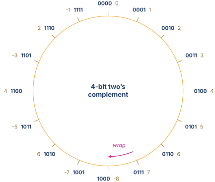
The table below enumerates the same sixteen patterns in tabular form so the unsigned and signed interpretations of each bit pattern sit side by side.
Table 2. Every 4-bit two’s complement pattern, its unsigned interpretation, and its signed interpretation. The high-order bit’s weight in the signed interpretation is -8.
| Bits | Unsigned | Signed | Bits | Unsigned | Signed |
|---|---|---|---|---|---|
| 0000 | 0 | 1000 | 8 | ||
| 0001 | 1 | 1001 | 9 | ||
| 0010 | 2 | 1010 | 10 | ||
| 0011 | 3 | 1011 | 11 | ||
| 0100 | 4 | 1100 | 12 | ||
| 0101 | 5 | 1101 | 13 | ||
| 0110 | 6 | 1110 | 14 | ||
| 0111 | 7 | 1111 | 15 |
The first virtue of two’s complement is that the all-zeros pattern is the unique encoding of zero. There is no and distinction.
The second virtue is the negation rule. To negate a two’s complement value, flip every bit and add one. To verify, apply the rule to (). Flipping every bit gives , and adding one gives , which the encoding table identifies as . The same rule applied to () flips to and adds one to give . The carry out of the high-order bit is discarded, so the four-bit result is , which is again . The encoding of zero is its own negation, as arithmetic demands.
The third virtue is the most important. A single -bit binary adder performs both unsigned and two’s complement signed addition correctly, without any sign-checking circuitry. The proof is in the next section.
Why two’s complement wins
Two’s complement arithmetic is arithmetic modulo . An -bit register holds one of distinct bit patterns. The unsigned interpretation maps those patterns to through . The signed interpretation maps the same patterns to through . The two interpretations differ only in where the cut between positive and negative falls, and the arithmetic obeys the same modular law in either case.
To see this, take any pair of -bit values whose unsigned interpretations are and and whose signed interpretations are and . The signed-to-unsigned relationship is
Adding two such values bit-by-bit through a normal -bit adder produces the unsigned sum
By the same modular identity, the bit pattern of this sum is also the encoding of modulo . As long as lies in the representable signed range, the result encodes the correct signed sum. As long as lies in the representable unsigned range, the result encodes the correct unsigned sum. The hardware adder does not care which interpretation the software intends. It computes the sum modulo either way.
This is the property that won. One adder serves both signed and unsigned arithmetic. Subtraction reduces to addition with negation, and negation is a bit-flip plus one. Comparison reduces to subtraction. The entire integer ALU is built around a single addition core, and the only conditional logic the ALU needs is the overflow detection that distinguishes the two failure modes.
06.Two’s Complement Arithmetic
Addition modulo
The previous section’s argument deserves to stand on its own because it is the equation the rest of the book will appeal to. The two’s complement value formula is
The hardware consequence of the equation above is that an -bit binary adder is enough. The same circuit, fed with bit patterns interpreted either as unsigned or as two’s complement signed, produces the correct sum under either interpretation. Modern instruction sets reflect this. RISC-V provides a single ADD instruction, not a separate ADDU. ARM AArch64 provides a single ADD (with optional flag-setting variants). x86 provides a single ADD. The signed and unsigned interpretations differ only in the flags consumed downstream.
Subtraction through negation and addition
Subtraction follows from negation and addition. To compute , the hardware computes . Negation in two’s complement is the flip-and-add-one operation, which on the level of circuitry is an array of inverters feeding a normal adder with a carry-in of . Figure 2 shows the operation applied to a positive 4-bit value to produce its negation.
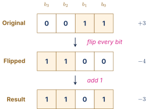
In practice, the integer ALU does not implement negation as a separate step. Subtraction is implemented as a + not(b) + 1, where the +1 comes from the carry-in input of the same adder that handles addition. The ALU therefore needs only one adder, one inverter array, and a one-bit multiplexer to select between and .
Sign extension and zero extension
A common operation in any modern ISA is to load a narrow value from memory into a wider register. A signed 8-bit byte loaded into a 32-bit register, for example, needs to be extended to 32 bits. The extension rule depends on whether the source value is signed or unsigned.
For zero extension, the extra high-order bits are filled with . The 8-bit unsigned value , which encodes , becomes the 32-bit value , which also encodes . The operation preserves the unsigned numerical value.
For sign extension, the extra high-order bits are filled with a copy of the source’s sign bit. The 8-bit signed value , which is the two’s complement encoding of , becomes the 32-bit value , which is also the encoding of . The operation preserves the signed numerical value.
Verifying sign extension takes a moment. By the equation above, the 8-bit value equals . The 32-bit value has , contributing , and bits through are all , contributing . The sum is . The signed value is preserved exactly.
RISC-V exposes the distinction in the load instruction mnemonics. A signed byte load is LB (load byte), which sign-extends. An unsigned byte load is LBU (load byte unsigned), which zero-extends. The same distinction appears in LH versus LHU for halfwords, and in LW versus LWU on the 64-bit variant where 32-bit loads into 64-bit registers need the extension choice [1].
Overflow detection
The carry out of the most significant bit signals unsigned overflow. It does not directly signal signed overflow. For signed arithmetic, the relevant condition is whether the result has a sign that contradicts the signs of the operands.
The rule for signed overflow on -bit addition is the following. A signed overflow occurs when two positive operands produce a negative-looking result, or when two negative operands produce a positive-looking result. Mathematically, signed overflow is exactly the condition where the carry-out of the high-order bit differs from the carry-into the high-order bit.
To illustrate, consider 4-bit two’s complement addition of (+6) and (+3). The expected result is , which is out of range for 4-bit signed arithmetic. The bit-level sum is
Two positive operands have produced a negative-looking result. The carry into bit 3 is (from the addition of the lower bits), but the carry out of bit 3 is . The two carries differ, signaling overflow. The processor sets the V flag on ARM or the OF flag on x86. RISC-V again omits the flag and expects software to detect the condition by inspecting the operand signs and the result sign.
07.Biased and Other Integer Representations
Two’s complement is the dominant signed integer representation, but two other encodings appear often enough in real architectures to deserve mention. The first is biased representation, which shows up in floating-point exponents. The second is binary-coded decimal, which lingers in financial software and a few legacy instruction-set features.
Biased (excess-K) representation
In a biased or excess-K representation, the stored bit pattern equals the encoded value plus a fixed constant called the bias. To recover the encoded value, subtract from the stored bit pattern interpreted as an unsigned binary integer. For an -bit field, is conventionally chosen as so that the encodable range straddles zero with one extra value on the positive side. The asymmetry therefore runs opposite to two’s complement, whose extra value falls on the negative side.
For and , the bit pattern encodes , the pattern encodes , and the pattern encodes . The representable range is through .
The virtue of biased representation is that the natural unsigned ordering of the bit patterns matches the numerical ordering of the encoded values. A pure bit-by-bit comparison of two bit patterns also compares their values. This is exactly the property the hardware in a floating-point comparator needs from the exponent field, and it is the reason IEEE 754 uses an excess-127 encoding for the 8-bit exponent of a 32-bit single-precision float, and an excess-1023 encoding for the 11-bit exponent of a 64-bit double-precision float [2]. The detailed treatment appears in Chapter 8.
Binary-coded decimal
A binary-coded decimal (BCD) encoding stores each decimal digit in a separate four-bit field. The decimal number encodes in three nibbles as , where , , and . Two flavors of BCD exist. Packed BCD stores two digits per byte, as in the example above. Unpacked BCD stores one digit per byte, with the upper nibble typically zero.
The encoding wastes 6 of the 16 patterns in each nibble, because through do not encode valid decimal digits. An -bit BCD field therefore encodes only distinct values where a pure binary encoding of the same width would encode . For four nibbles (one 16-bit half-word), BCD gives 10,000 distinct values while binary gives 65,536. The space inefficiency is the price for one specific advantage: BCD-to-decimal-string conversion is trivial, since each nibble translates to one decimal character.
BCD is used in two settings. The first is financial software, where the absence of rounding error is more important than the storage cost. Decimal arithmetic in BCD is exact for decimal fractions, whereas binary floating-point cannot represent exactly. Languages with decimal arithmetic support (COBOL, PL/SQL, the decimal type in modern Python and C#) use a form of BCD internally.
The second setting is the legacy x86 AAA (ASCII Adjust After Addition) family of instructions, which date to the original 8086 and were retained for backward compatibility through the 32-bit era. [3] The instructions never operated in 64-bit long mode, and AMD removed them from the AMD64 architecture when the 64-bit extensions shipped [4]. New software does not use them.
08.Characters and Text Encodings
So far the bit patterns have encoded numbers. The same approach encodes text. The architect assigns each character of interest to a numerical code, and the same registers and memories that store integers store the codes. The historical evolution from the earliest 6-bit character codes through ASCII to modern Unicode is worth tracing because each step reflects a real architectural constraint of its era.
The need for text encoding
A character is an abstract symbol, like the letter A or the digit 5 or the punctuation mark ,. The hardware does not natively know what these symbols are. The software designates a mapping from each symbol of interest to a numerical code, and the hardware stores and moves the codes. A display device knows how to render the code, a keyboard knows how to produce the code, and a network protocol knows how to ship the code from one machine to another. The mapping is a standard, and its choice has lasting consequences.
ASCII and its limits
The American Standard Code for Information Interchange, abbreviated ASCII, was published in 1963 and updated through 1986. ASCII assigns 7-bit codes to 128 characters. The range divides into 33 non-printing control codes (0x00 through 0x1F and 0x7F) and 95 printable characters (0x20 through 0x7E).
The structure of the printable range is deliberate. The table below lists the seven blocks. The digits 0 through 9 sit in the range 0x30 through 0x39, so subtracting 0x30 from the code of a digit character yields the digit’s numeric value. The uppercase letters A through Z sit in 0x41 through 0x5A, and the lowercase letters a through z sit in 0x61 through 0x7A. The offset between an uppercase letter and its lowercase counterpart is exactly 0x20, which means that toggling bit 5 of an ASCII letter converts between cases. This is not coincidence. The committee that designed ASCII wanted the bit-level structure to support common operations cheaply on the hardware of the time.
Table 3. Structure of the printable ASCII range. The exact bit offset between uppercase and lowercase letters is 0x20, which sets bit 5 of the code.
| Block | Hex range | Decimal range |
|---|---|---|
| Space and punctuation | 0x20–0x2F | 32–47 |
| Digits 0–9 | 0x30–0x39 | 48–57 |
| More punctuation | 0x3A–0x40 | 58–64 |
| Uppercase letters | 0x41–0x5A | 65–90 |
| Brackets, backslash | 0x5B–0x60 | 91–96 |
| Lowercase letters | 0x61–0x7A | 97–122 |
| Final punctuation | 0x7B–0x7E | 123–126 |
ASCII fit comfortably in 7 bits. Most machines stored each ASCII character in one 8-bit byte with the high-order bit clear. The spare bit was sometimes used for parity in transmission and sometimes left as a vestigial zero.
The seven-bit space was adequate for English-language text and a few common symbols. It was not adequate for accented Latin characters, for Cyrillic, for Greek, for Chinese, Japanese, or Korean, for any non-Latin script at all. By the 1980s the limitation had become a serious obstacle for software shipped internationally. The next decade was spent finding a successor.
ISO-8859 and the code page era
The first wave of solutions used the spare high bit of each byte to extend the encoding to 256 characters. Different code pages were defined for different language regions. The ISO 8859 family of standards specified sixteen such code pages, each preserving ASCII in the lower half and adding a region-specific set of additional characters in the upper half. ISO 8859-1 (Latin-1) covered Western European languages. ISO 8859-5 covered Cyrillic. ISO 8859-7 covered Greek.
The code page approach worked badly. A single document could not mix characters from different code pages, since the upper half of the byte meant different things in different encodings. A web page could not display a name with both a German umlaut and a Greek letter without switching encodings mid-stream. The same file, opened on a machine configured for a different code page, displayed garbled text. The industry needed a single encoding that could represent every script in use.
Unicode and UTF-8
The Unicode Consortium answered the question. The Unicode standard assigns a unique integer called a code point to every character in every script. Code points are written in the form U+XXXX, where the digits are hexadecimal. The letter A is U+0041, the same value as its ASCII code. The Greek lowercase lambda is U+03BB. The grinning-face emoji is U+1F600. The current Unicode standard, version 15.1, defines about 149,000 code points covering 161 scripts [5].
The code point alone does not specify the byte sequence used to store a string. The mapping from code points to bytes is the encoding, and several Unicode encodings are in use. The dominant one, by an enormous margin, is UTF-8.
UTF-8 encodes each code point as a sequence of one to four bytes. The number of bytes depends on the code point’s value, with small code points using fewer bytes. The encoding rules are summarized in Figure 3. The leading bits of the first byte identify the byte count, and the subsequent bytes each begin with the bit pattern to mark them as continuation bytes. The remaining bits, read across the byte sequence, spell out the code point.
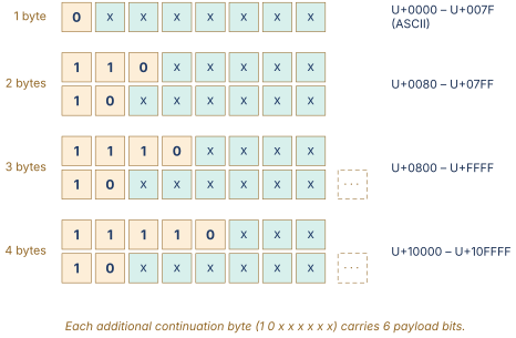
The 1-byte form encodes code points U+0000 through U+007F using the bit pattern . The seven payload bits carry the code point directly. This range coincides with ASCII, and the encoded byte is identical to the ASCII code. Plain ASCII text is therefore valid UTF-8 text without modification, which was the central design constraint when UTF-8 was specified in 1992 and later standardized in RFC 3629 [6].
The 2-byte form encodes code points U+0080 through U+07FF. The first byte has the bit pattern , and the second has . The eleven payload bits together carry the code point. The lambda character U+03BB encodes as follows. The code point is decimal, which is in ten bits and therefore once zero-padded to the eleven payload bits. Splitting into a five-bit and a six-bit group gives and . Wrapping the two groups in the templates produces . Verification by decoding strips the prefixes, concatenates the payloads, and recovers , which equals 955.
The 3-byte form encodes U+0800 through U+FFFF and is used for the remaining characters in the Basic Multilingual Plane, including Chinese, Japanese kanji, Korean hangul, and many others. The first byte has the form , followed by two continuation bytes. The 4-byte form encodes U+10000 through U+10FFFF, where most of the emoji and many historical scripts live. The grinning-face emoji U+1F600 falls in this range and encodes as the four bytes .
UTF-8 has several properties that contributed to its dominance. ASCII is a strict subset, so existing ASCII text is automatically valid UTF-8. The encoding is self-synchronizing, because any byte that does not begin with is the start of a character. The encoding is order-preserving, in the sense that comparing two UTF-8 byte strings byte-by-byte produces the same ordering as comparing the underlying code points. The encoding is ASCII-safe in network protocols, because no UTF-8 byte sequence contains a NUL byte (0x00) unless the original text contained U+0000. As of 2026 UTF-8 accounts for more than 98 percent of all web pages, and it is the default encoding of most modern programming languages including Rust, Go, Swift, and Python 3.
UTF-16 and UTF-32
Two other Unicode encodings appear in real systems. UTF-16 uses 16-bit code units. Code points in the Basic Multilingual Plane (U+0000 through U+FFFF) take one 16-bit code unit. Code points above U+FFFF use a pair of 16-bit code units called a surrogate pair, drawn from a reserved range U+D800 through U+DFFF that is itself not a valid character. The encoding is the historical default of the Windows API, the Java Virtual Machine, and the JavaScript string type. New systems generally prefer UTF-8 for storage and transport, with UTF-16 retained for in-memory representation in legacy stacks.
UTF-32 uses one 32-bit code unit per code point. The encoding has the virtue of constant-time indexing into a string by code point, but the cost of four bytes per character even for ASCII has prevented it from spreading. It appears occasionally as an internal representation in libraries that need random-access indexing, but rarely on disk or on the wire.
09.Endianness
The byte-order problem
A 32-bit integer occupies four bytes of memory. The processor addresses memory one byte at a time, but it reads or writes the 32-bit integer as a single unit. There is a choice of how to order the four bytes inside the address space. Should the least significant byte sit at the lowest address, or should the most significant byte sit at the lowest address? Both choices work, and both are in use.
Little-endian and big-endian
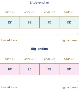
Little-endian byte order places the least significant byte at the lowest address. The 32-bit integer is stored as the byte sequence starting from the lowest address. The ordering is the reverse of the natural left-to-right reading order when the integer is written in hexadecimal, which is why some authors call it “backwards” on first encounter. The little-endian convention is used by Intel x86 and x86-64, by ARM in its default operating mode on essentially every modern Linux, macOS, iOS, Android, and Windows system, and by RISC-V in its standard configuration.
Big-endian byte order places the most significant byte at the lowest address. The same integer is stored as the byte sequence starting from the lowest address. The ordering matches the natural reading order of the hexadecimal representation. Big-endian was used by the IBM System/360 and descendants, by the original Motorola 68000 family, by classic SPARC, by the PowerPC family in its default mode, and by most network protocols.
Figure 4 shows the same 32-bit value laid out in memory under both conventions. The byte at the lowest address differs between the two layouts.
The choice has practical consequences for code that reinterprets memory. A program that writes a 32-bit integer into a memory buffer and then reads four individual bytes out of the same buffer will see different byte values depending on the endianness of the machine. Code that reads or writes file formats or network packets must therefore either use endianness-explicit serialization or must check the endianness of the host at runtime.
A few architectures support both. ARM AArch64 has a configurable endianness setting controlled by a system register, although in practice essentially every operating system fixes the mode to little-endian at boot. PowerPC supports a bi-endian mode that is selected per process. RISC-V has been little-endian since the original specification. A big-endian variant was added later but is rarely deployed.
Endianness in network protocols
A network packet leaves one machine and arrives at another. If the two machines use different endianness, a multi-byte field written naively at the sender will be read incorrectly at the receiver. The Internet protocol family solves this by specifying a fixed byte order for all multi-byte protocol fields. The chosen order is big-endian, and the term network byte order is shorthand for big-endian.
The Unix C library exposes the conversion through four standard functions. htons converts a 16-bit value from host byte order to network byte order. htonl does the same for a 32-bit value. ntohs and ntohl convert in the reverse direction. On a little-endian host (the common case for modern processors), these functions perform a byte swap. On a big-endian host, they are identity operations. The code is portable across endianness because the function names abstract away the question of which way the conversion goes.
The listing below shows a short C program that prints a 32-bit value byte by byte, demonstrating the endianness of the host machine.
A C program that reveals the host’s endianness by examining the raw byte representation of a 32-bit integer.
#include <stdio.h>
#include <stdint.h>

int main(void) {
    uint32_t value = 0xDEADBEEF;
    uint8_t  *bytes = (uint8_t *)&value;
    printf("value         = 0x%08X\n", value);
    printf("bytes[0..3]   = %02X %02X %02X %02X\n",
          bytes[0], bytes[1], bytes[2], bytes[3]);
    if (bytes[0] == 0xEF) {
        printf("host is little-endian\n");
    } else if (bytes[0] == 0xDE) {
        printf("host is big-endian\n");
    } else {
        printf("host is something unusual\n");
    }
    return 0;
}
A complementary Python snippet using the standard int methods appears in the listing below.
Python equivalents of the C byte-order test. The int.to_bytes method takes the byte order as an explicit argument.
| value = 0xDEADBEEF | |
| print(f"big-endian = {value.to_bytes(4, 'big').hex(' ')}") | |
| print(f"little-endian = {value.to_bytes(4, 'little').hex(' ')}") | |
| print(f"bit length = {value.bit_length()} bits") |
The two listings together establish the convention used in the rest of the book. Whenever a chapter says “the 32-bit value at address ”, the reader should understand that the bytes at addresses through encode the value according to the endianness of the architecture under discussion. For RISC-V, ARM under Linux, and x86-64, that endianness is little-endian.
10.Looking Ahead
The encodings developed in this chapter underpin nearly every subsequent chapter. Boolean algebra in Chapter 4 works on the same bit patterns, with logical rather than arithmetic operations. The integer ALU in Chapter 5 performs two’s complement addition, subtraction, and comparison on these patterns, and the multipliers and dividers in Chapter 7 build on the same encoding. The floating-point hardware in Chapter 8 reuses biased representation for the exponent field, and the sign-extension machinery built in this chapter reappears for the significand shift logic. Memory addressing in Part IV treats addresses as unsigned 64-bit integers and lays out data structures byte by byte according to the architecture’s endianness convention. Instruction encoding in Chapter 13 packs opcode, register specifiers, and immediate fields into 32-bit binary patterns that the fetch logic in Chapter 25 reads. The reader who has worked through this chapter can take all of those representations as given.
The chapter has also introduced the discipline that the book uses to write about bit-level structure. Hexadecimal for register dumps, two’s complement for signed integers, IEEE 754 for floating-point, UTF-8 for text, and little-endian byte order for memory layout. These are the running conventions. The few cases where another convention applies are called out explicitly in context.
11.Worked Examples
12.Exercises
References
- [1]Waterman, Andrew and Asanovi\'c (2024). “The RISC-V.”
- [2]IEEE (2019). “IEEE.” IEEE. doi:10.1109/IEEESTD.2019.8766229
- [3](2024). “Intel.”
- [4](2024). “AMD64.”
- [5](2023). “The Unicode.”
- [6]Yergeau, Fran\c c (2003). “UTF-8.” Internet Engineering Task Force. doi:10.17487/RFC3629