Hardware Description Languages
September 8, 202623 min readbeginner
Up to this point in the book, every circuit has been specified by a schematic, a truth table, or a state diagram drawn on paper. That approach works for a 4-bit adder or a traffic-light FSM with five states…
Up to this point in the book, every circuit has been specified by a schematic, a truth table, or a state diagram drawn on paper. That approach works for a 4-bit adder or a traffic-light FSM with five states. It does not work for a billion-transistor processor. No human can draw, inspect, or verify a schematic with a million gates. The tool that makes modern chip design possible is the hardware description language (HDL), a textual notation for expressing what a circuit does (behavior) or how it is built (structure). The HDL text is readable by both humans and software tools. The tools simulate it, verify it, and ultimately synthesize it into the gate-level netlists of Chapter 9.
This chapter introduces the four languages the reader will encounter most often: Verilog, SystemVerilog, VHDL, and Chisel. The first three are IEEE-standardized HDLs that describe hardware directly. Chisel is a hardware construction language embedded in Scala that generates synthesizable Verilog, trading direct hardware description for the software engineering benefits of a host programming language (parameterization, type safety, code reuse). The chapter focuses on the concepts common to all four: the distinction between simulation and synthesis, the register-transfer level of abstraction, combinational versus sequential modeling, and the role of testbenches in verification.
01.Why Not Just Write Software?
A reasonable first question is: why not describe hardware in a conventional programming language like C or Python? The answer lies in a fundamental difference between software and hardware.
A software program executes sequentially. Statement A finishes before statement B begins (ignoring threads for the moment). Hardware operates concurrently. Every gate on a chip is computing simultaneously, and the output of one gate changes the input of another within the same clock cycle. An HDL must express this parallelism naturally.
Verilog and VHDL solve the problem with concurrent assignment. Every assign statement in Verilog and every signal assignment in VHDL describes a wire that is continuously driven. All such assignments are active at the same time, just as all the gates on a chip are active at the same time. The order in which the assignments appear in the source file does not matter for combinational logic, because the simulator evaluates them based on signal dependencies, not textual order.
Chisel takes a different approach. Because it is embedded in Scala, the user writes Scala code that, when executed, constructs a graph of hardware nodes (wires, registers, muxes, operators). The Scala program itself runs sequentially (it is ordinary software), but its output is a circuit graph that represents concurrent hardware. The distinction between the “generator program” (sequential Scala) and the “generated hardware” (concurrent digital circuit) is central to understanding Chisel.
02.Simulation and Synthesis
An HDL description serves two very different purposes, and understanding the boundary between them is essential.
Simulation executes the HDL model on a computer to verify that the circuit produces the correct outputs. The simulator reads the HDL source, builds an internal data structure (an event queue for event-driven simulators, or a flattened graph for cycle-based simulators), applies input stimuli from a testbench, and reports the outputs. Simulation can model delays, power, and even analog behavior, but its primary job during RTL development is functional correctness.
Synthesis translates the HDL description into a gate-level netlist. The synthesis tool reads the same HDL source that the simulator reads, but it interprets it differently. It maps behavioral constructs (if-else, case, always_ff) to standard cells (muxes, flip-flops, gates) from a target technology library. Not every legal HDL construct is synthesizable. File I/O, system tasks ($display, $readmemh), and time delays (#10) are simulation-only features that the synthesis tool ignores or rejects.
Table 1. Simulation-only versus synthesizable HDL constructs.
| Construct | Simulation | Synthesis |
|---|---|---|
assign (continuous) | Yes | Yes |
always_comb block | Yes | Yes |
always_ff block | Yes | Yes |
initial block | Yes | No |
$display / $monitor | Yes | No |
Time delay (#10) | Yes | No |
File I/O ($fopen) | Yes | No |
for loop (constant bounds) | Yes | Yes (unrolled) |
while loop (variable bounds) | Yes | No |
A well-disciplined HDL codebase separates synthesizable design code (the hardware) from non-synthesizable testbench code (the verification). The testbench instantiates the design module, drives its inputs, and checks its outputs. The testbench can use every language feature. The design module stays within the synthesizable subset.
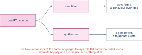
Figure 1 shows the split.
03.Verilog and SystemVerilog
Verilog was designed in 1984 by Phil Moorby at Gateway Design Automation, acquired by Cadence in 1990, and standardized as IEEE 1364 in 1995 (revised 2001, 2005). SystemVerilog, standardized as IEEE 1800, merges Verilog with extensive verification features (classes, randomization, assertions, functional coverage) and improved synthesis semantics. In practice, the industry has moved almost entirely to SystemVerilog. Pure Verilog is encountered mainly in legacy codebases and in educational settings that want a simpler starting point.
Modules and ports
The basic unit of hierarchy in Verilog and SystemVerilog is the module. A module declares its name, its ports (inputs and outputs), and its body:
A 2-to-1 multiplexer in SystemVerilog
| module mux2 #(parameter WIDTH = 8) ( | |
| input logic [WIDTH-1:0] a, b, | |
| input logic sel, | |
| output logic [WIDTH-1:0] y | |
| ); | |
| assign y = sel ? b : a; | |
| endmodule |
The #(parameter WIDTH = 8) clause makes the module parameterizable. A single source description generates a 1-bit mux, a 32-bit mux, or a 64-bit mux depending on the value passed at instantiation. Parameterization is SystemVerilog’s primary mechanism for hardware reuse.
The assign statement describes a wire: y is continuously driven by the ternary expression sel ? b : a. This is combinational logic. No clock, no flip-flop, no stored state.
Combinational logic with always_comb
For logic too complex for a single assign, SystemVerilog provides the always_comb block. The block executes whenever any signal it reads changes, and the synthesis tool interprets it as combinational logic:
ALU operation select using always_comb
| always_comb begin | |
| case (op) | |
| 2'b00: result = a + b; | |
| 2'b01: result = a - b; | |
| 2'b10: result = a & b; | |
| 2'b11: result = a | b; | |
| endcase | |
| end |
Sequential logic with always_ff
Clocked (sequential) logic is described with always_ff:
An 8-bit register with synchronous reset
| always_ff @(posedge clk) begin | |
| if (rst) | |
| q <= 8'h00; | |
| else if (en) | |
| q <= d; | |
| end |
The @(posedge clk) sensitivity list tells the synthesis tool this block describes flip-flops clocked on the rising edge. The non-blocking assignment operator <= is mandatory inside always_ff. It means “schedule this assignment to take effect at the end of the current simulation time step,” which models the real behavior of a flip-flop: the output does not change until after the clock edge.
Structural instantiation
Modules can instantiate other modules, building a design hierarchy:
Instantiating three mux2 modules to build a 4-to-1 mux
module mux4 #(parameter WIDTH = 8) (
  input  logic [WIDTH-1:0] a, b, c, d,
  input  logic [1:0]       sel,
  output logic [WIDTH-1:0] y
);
  logic [WIDTH-1:0] low, high;

  mux2 #(.WIDTH(WIDTH)) lo (
    .a(a), .b(b), .sel(sel[0]), .y(low));
  mux2 #(.WIDTH(WIDTH)) hi (
    .a(c), .b(d), .sel(sel[0]), .y(high));
  mux2 #(.WIDTH(WIDTH)) final_mux (
    .a(low), .b(high), .sel(sel[1]), .y(y));
endmodule
Each mux2 instance is a copy of the module with its ports connected by name (.a(a) means “connect port a of the instance to signal a of the enclosing module”). The resulting circuit is three physical muxes wired together, not three sequential function calls. The distinction matters: all three muxes evaluate concurrently.
04.VHDL
VHDL (IEEE 1076) was developed in the 1980s under the US Department of Defense VHSIC (Very High Speed Integrated Circuit) program. It uses Ada-like syntax with explicit type declarations, making it more verbose than Verilog but also more strongly typed. VHDL remains dominant in European industry and in defense and aerospace applications, and it holds a significant share of FPGA workflows targeting Xilinx (AMD) and Intel (Altera) parts.
The same 2-to-1 multiplexer in VHDL
library ieee;
use ieee.std_logic_1164.all;

entity mux2 is
  generic (WIDTH : positive := 8);
  port (
    a, b : in  std_logic_vector(WIDTH-1 downto 0);
    sel  : in  std_logic;
    y    : out std_logic_vector(WIDTH-1 downto 0)
  );
end entity mux2;

architecture rtl of mux2 is
begin
  y <= b when sel = '1' else a;
end architecture rtl;
VHDL separates the entity (the port interface) from the architecture (the implementation). A single entity can have multiple architectures, a feature useful in simulation (one architecture for behavioral modeling, another for structural gate-level modeling) but rarely exploited in synthesis flows.
The key conceptual mapping from SystemVerilog to VHDL is straightforward: module becomes entity plus architecture, parameter becomes generic, assign becomes a concurrent signal assignment, always_comb becomes a process(all) with complete sensitivity, and always_ff becomes a process(clk) with a rising_edge(clk) guard.
Table 2. Side-by-side comparison of SystemVerilog and VHDL constructs.
| SystemVerilog | VHDL |
|---|---|
module | entity + architecture |
parameter | generic |
logic / wire | std_logic / signal |
assign y = expr; | y <= expr; (concurrent) |
always_comb | process(all) |
always_ff @(posedge clk) | process(clk) ... rising_edge(clk) |
<= (non-blocking) | <= (signal assignment) |
case | case ... is when |
05.Chisel: Hardware Construction in Scala
Chisel (Constructing Hardware in a Scala Embedded Language) was developed at UC Berkeley alongside the RISC-V project. It is not an HDL in the traditional sense. It is a Scala library that, when executed, constructs a hardware graph and emits synthesizable Verilog (or a lower-level intermediate representation called FIRRTL, which is then lowered to Verilog). The distinction between the “generator” (the Scala program) and the “generated hardware” (the Verilog output) is fundamental.
Modules and IO
A Chisel module extends the Module base class and declares its ports through an IO bundle:
A 2-to-1 multiplexer in Chisel
import chisel3._

class Mux2(val width: Int = 8) extends Module {
  val io = IO(new Bundle {
    val a   = Input(UInt(width.W))
    val b   = Input(UInt(width.W))
    val sel = Input(Bool())
    val y   = Output(UInt(width.W))
  })

  io.y := Mux(io.sel, io.b, io.a)
}
The width parameter is a plain Scala constructor argument. When the Chisel elaboration engine runs, it substitutes the parameter value and produces a Verilog module with the corresponding bit widths. This is the generator pattern: a single Scala class produces different hardware for different parameter values.
The := operator is Chisel’s connection operator (it replaces Verilog’s assign and VHDL’s concurrent <=). It does not mean “sequential assignment.” It means “wire the left-hand side to the right-hand side.”
Combinational and sequential logic
Chisel separates combinational and sequential logic by construction. Any expression using Chisel operators (+, -, &, |, Mux, etc.) without a Reg wrapper is combinational. A RegNext or RegInit wraps a value in a flip-flop:
An 8-bit register with synchronous reset in Chisel
import chisel3._

class Reg8 extends Module {
  val io = IO(new Bundle {
    val d  = Input(UInt(8.W))
    val en = Input(Bool())
    val q  = Output(UInt(8.W))
  })

  val reg = RegInit(0.U(8.W))  // reset value 0
  when (io.en) {
    reg := io.d
  }
  io.q := reg
}
No always_ff keyword, no sensitivity list, no non-blocking assignment operator. The RegInit call creates a flip-flop. The when block is syntactic sugar that compiles to a mux feeding the register’s input. The clock and reset are implicit (carried by the Module base class).
Generators versus RTL
The single most important idea in Chisel is the generator pattern. Because Chisel is embedded in a full programming language, the designer can use loops, conditionals, data structures, and functional programming to parameterize hardware in ways that Verilog’s generate and VHDL’s for generate cannot express cleanly.
Consider a parameterizable -to-1 multiplexer tree:
A parameterized mux tree generator in Chisel
import chisel3._
import chisel3.util._

class MuxTree(val n: Int, val w: Int) extends Module {
  require(isPow2(n), "n must be a power of 2")
  val io = IO(new Bundle {
    val ins = Input(Vec(n, UInt(w.W)))
    val sel = Input(UInt(log2Ceil(n).W))
    val out = Output(UInt(w.W))
  })

  io.out := io.ins(io.sel)
}
The Vec type creates an indexed collection of hardware signals. The io.ins(io.sel) expression generates a mux tree that selects one of the n inputs based on sel. Change n from 4 to 64 and the elaboration engine produces a deeper tree with more mux stages, all from the same module definition. In Verilog, the equivalent would require nested generate for loops with careful index arithmetic.
Table 3. Comparison of language features across the four HDLs covered in this chapter.
| Feature | Verilog | SystemVerilog | VHDL | Chisel |
|---|---|---|---|---|
| IEEE standard | 1364 | 1800 | 1076 | None |
| Typing | Weak | Moderate | Strong | Strong |
| Parameterization | parameter | parameter | generic | Scala values |
| Verification | Basic | Rich | Moderate | Scala tests |
| Generators | generate | generate | for generate | Full Scala |
| Output | Direct | Direct | Direct | Emits Verilog |
06.The RTL Design Pattern
Regardless of the language, the vast majority of synchronous digital designs follow the same structural pattern: a collection of registers (flip-flops) separated by blocks of combinational logic. On each clock edge, every register captures its input. The combinational logic between registers computes the next values. This is the register-transfer level (RTL) abstraction, and it maps directly to the physical organization of a synchronous chip [1].
The RTL pattern has three consequences for HDL coding style:
First, separate combinational logic from sequential logic. In SystemVerilog, this means using always_comb for the next-state logic and always_ff for the register update. In Chisel, this means computing the next value as a combinational expression and assigning it to a Reg. Mixing the two in a single undifferentiated block obscures the design intent and complicates synthesis.
Second, use only the synthesizable subset. Testbench code can use any language feature. Design code stays within the RTL subset so that the synthesis tool can map it to gates and flip-flops.
Third, design for timing. Every signal path from a register output through combinational logic to the next register input must meet the setup constraint of Chapter 6. The architect must be aware of which operations are “big” (a 64-bit multiply, a content-addressable memory lookup) and will be the critical path in the synthesized netlist.
07.Testbenches and Verification
A testbench is the non-synthesizable wrapper that drives inputs into the design under test (DUT), observes its outputs, and checks them against expected values. In the project and lab chapters of this book, the testbench is always written in the same language as the DUT (SystemVerilog testbenches for SystemVerilog designs, Scala/ChiselTest for Chisel designs).
The simplest testbench style is directed testing: the engineer writes a sequence of input vectors and the expected outputs. The testbench applies each vector, waits for the output to settle, and compares:
A directed testbench for the 2-to-1 mux
module mux2_tb;
  logic [7:0] a, b, y;
  logic sel;

  mux2 #(.WIDTH(8)) dut (
    .a(a), .b(b), .sel(sel), .y(y));

  initial begin
    a = 8'hAA; b = 8'h55; sel = 0;
    #10;
    assert (y == 8'hAA) else $error("FAIL: sel=0");

    sel = 1;
    #10;
    assert (y == 8'h55) else $error("FAIL: sel=1");

    $display("All tests passed");
    $finish;
  end
endmodule
Directed tests verify specific scenarios. More advanced verification uses constrained-random testing, where the testbench generates random input sequences within defined constraints and a scoreboard checks every output against a behavioral reference model. That approach scales to the complexity of modern processors and is the standard practice in the industry, though it is beyond the scope of this introductory chapter.
08.Choosing a Language
There is no single “best” HDL. The choice depends on the project and the ecosystem.
SystemVerilog is the default for ASIC design at most semiconductor companies. EDA tools from Synopsys, Cadence, and Siemens all support it as a first-class citizen. Its C-like syntax is familiar to software engineers.
VHDL remains preferred in European industry, defense and aerospace, and some FPGA workflows. Its strong typing catches errors at compile time that Verilog would silently pass through.
Chisel is gaining traction in the academic and open-source hardware communities, particularly around the RISC-V ecosystem. The UC Berkeley Rocket Chip, BOOM (Berkeley Out-of-Order Machine), and many other research processors are written in Chisel. Its generator model is a natural fit for parameterizable IP blocks and design-space exploration.
Verilog (plain 1364) is still encountered in legacy IP and in introductory courses. Any SystemVerilog tool can compile Verilog-2001 code, so there is no compatibility barrier.
The project chapter that follows (Chapter 11) uses Chisel because it offers the most concise notation for the 32-bit ALU project and because its test harness integrates directly with the simulation tool (Verilator). Chapter 12 uses the open-source HDL workflow (Yosys for synthesis, Icarus Verilog for simulation, Verilator for fast cycle-accurate simulation) that supports both Verilog and SystemVerilog.
09.Common Modeling Patterns
Regardless of the language chosen, a small set of structural patterns appears in every RTL codebase. Recognizing them accelerates both reading and writing HDL.
The mux chain. A priority-encoded if-else cascade maps to a chain of 2-to-1 muxes. The first condition has the highest priority. If the conditions are mutually exclusive (as in a one-hot-encoded opcode), the synthesis tool can optimize the chain into a flat mux with one hot select.
The registered output. A combinational block followed by a register. In SystemVerilog this is a pair of blocks: an always_comb that computes the next value and an always_ff that captures it. In Chisel this is a combinational expression assigned to a Reg. This pattern is the basic unit of the RTL abstraction: compute, then store.
The enabled register. A register that updates only when an enable signal is asserted. Otherwise it holds its previous value. In SystemVerilog: if (en) q <= d; inside an always_ff block. In Chisel: when (en) { reg := d }. This pattern is the register file write port, the pipeline stall mechanism, and the cache-line valid bit.
The counter with terminal count. A register that increments on each enabled clock edge and wraps to zero when it reaches a maximum value. A comparator on the current count generates a terminal-count pulse that other logic uses as a “done” signal. This pattern is the timer, the burst counter in a memory controller, and the round counter in an iterative divider.
The shift register. A chain of registers where each register’s output feeds the next register’s input. Data enters at one end and exits at the other end cycles later, where is the number of stages. This pattern is the delay line, the serial-to-parallel converter, and the LFSR pseudo-random generator of Chapter 6.
10.Looking Ahead
This chapter has introduced the four hardware description languages that the reader will use throughout the rest of the book and in any career that touches digital hardware. The key ideas transcend any single language: the RTL abstraction, the separation of combinational and sequential logic, the distinction between simulation and synthesis, and the generator pattern for parameterizable hardware.
Chapter 11 puts these ideas into practice with a hands-on project: building a 32-bit ALU in Chisel, simulating it with Verilator, and viewing the waveforms in Surfer. Chapter 12 follows with a lab on the open-source HDL workflow that adds Yosys (synthesis) and Icarus Verilog (event-driven simulation) to the toolchain.
11.Worked Examples
12.Exercises
References
- [1]Harris, Sarah L. and Harris, David Money (2021). “Digital Design and Computer Architecture.” Morgan Kaufmann.