Pipeline Hazards
September 8, 202627 min readintermediate
The 5-stage pipeline of Chapter 29 achieves one instruction per cycle in steady state, assuming nothing ever prevents the next instruction from advancing into the next stage. That assumption is rarely true…
The 5-stage pipeline of Chapter 29 achieves one instruction per cycle in steady state, assuming nothing ever prevents the next instruction from advancing into the next stage. That assumption is rarely true. Real programs contain data dependencies, branches, and occasional resource conflicts that force the pipeline to delay instructions or to throw away work it has already started. The cycles lost to these disturbances are the gap between the pipeline’s nominal CPI of 1.0 and the CPI an actual program achieves.
This chapter classifies those disturbances and describes the hardware techniques that minimize their cost. The classification divides hazards into three categories. Structural hazards arise from finite hardware. Data hazards arise from instruction-level dependencies. Control hazards arise from branches that change the fetch path. The techniques fall into two families. Stalling delays the affected instruction until the conflict resolves. Forwarding routes results from where they are produced to where they are needed, without waiting for writeback.
The treatment is concrete throughout. Each hazard is illustrated with a short RV32I sequence, a pipeline diagram showing the stall pattern, and a description of the hardware that detects and resolves the conflict. Branch prediction, the most important technique for reducing control-hazard cost, receives only a preview here, since modern predictors are intricate enough to deserve chapters of their own (Chapters 55 and 56).
01.Why Hazards Exist
The 5-stage pipeline assumes that every instruction is independent of the four instructions ahead of it. Real code is not like that. A typical RV32I instruction sequence has dependencies every few instructions. The compiler tries to arrange instructions so that dependent ones are spaced out, but spacing is limited by the program’s actual structure. Loops are dense. Stack-frame setup is dense. Pointer chasing is dense.
02.Structural Hazards
A structural hazard occurs when two instructions in different pipeline stages need the same hardware resource in the same cycle. The classic 5-stage RISC-V pipeline avoids most structural hazards by design. The instruction memory and data memory are separate ports (the so-called Harvard architecture Chapter 25), so IF and MEM cannot collide. The register file has two read ports and one write port, so ID can read while WB writes in the same cycle. The ALU is in EX only, the comparator is in EX only, and the load-extension unit is in MEM only.
Where structural hazards do occur, the typical causes are shared-memory designs (one memory port serving both IF and MEM, common in embedded cores) or a multi-cycle execution unit (a divider or a multi-cycle multiplier) that cannot accept a new operation every cycle.
Single-Port Memory
Suppose IF and MEM share a single memory port. Cycle 4 in the diagram below has the first instruction (a load) in MEM trying to read data, while the fourth instruction is in IF trying to read its instruction word. Both target the same port. The instruction in IF must stall for one cycle.
The IF of the fourth instruction is delayed by one cycle (the -- in the diagram is the stall). The fix at design time is to use separate instruction and data memories, which is what the canonical 5-stage RISC-V pipeline does.
Multi-Cycle Functional Units
A divider that takes 16 cycles to produce its result cannot accept a new DIV every cycle. If two divides arrive back to back, the second one must stall in ID until the first one finishes. The control logic detects this case by checking a “divider busy” flag.
03.Data Hazards: The Three Sub-Types
A data hazard occurs when one instruction reads or writes a register that an earlier-issued, not-yet-completed instruction is also reading or writing. The classification by Bernstein separates these into three kinds, named by the order of access:
-
Read-After-Write (RAW). Instruction reads a register that an earlier instruction writes. This is a true dependence. The value of ’s read depends on having finished its write.
-
Write-After-Read (WAR). Instruction writes a register that an earlier instruction reads. In a strictly in-order pipeline like the 5-stage design, this hazard cannot occur, because reads its operand in ID before even enters ID. WAR becomes important only in out-of-order machines, and the full treatment is in Chapter 51 on register renaming.
-
Write-After-Write (WAW). Instructions and both write the same register. The architectural state must reflect ’s write, not ’s. In strictly in-order pipelines this is also automatic: writes happen in program order in WB. WAW is again an out-of-order concern.
04.RAW Hazards Without Forwarding
Consider the sequence
Back-to-back RAW dependence
| ADD x10, x11, x12 ; writes x10 in WB at cycle 5 | |
| SUB x13, x10, x14 ; reads x10 in ID at cycle 3 |
The first instruction writes x10 in WB. In the canonical timing the WB write lands in the register file during cycle 5, and the register file’s internal write-through makes it visible to a read in the same cycle. The second instruction reads x10 in ID at cycle 3. The value of x10 that ID reads at cycle 3 is the old value, because the ADD’s new value will not land in the register file for two more cycles.
Without any hardware countermeasure, the pipeline silently produces a wrong answer. The fix without forwarding is to stall the second instruction in ID until the first has written back. That requires inserting bubbles so that the SUB’s ID happens in the same cycle as the ADD’s WB or later.
Table 2. RAW stall with no forwarding
| Cycle | 1 | 2 | 3 | 4 | 5 | 6 | 7 |
|---|---|---|---|---|---|---|---|
ADD x10 | IF | ID | EX | MEM | WB | ||
SUB x13 | IF | ID | -- | -- | EX | MEM |
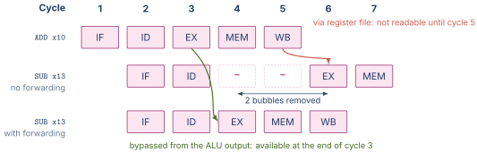
Figure 1 redraws that table with the consumer shown twice, so the route the value takes in each case is visible rather than inferred.
In this naive scheme, the SUB sits in ID for three cycles (cycles 3, 4, 5), reading the register file three times. Only at cycle 5, after the ADD’s WB has updated x10, does the SUB see the correct value. The penalty for every back-to-back RAW dependence is two bubbles. On real code with many such dependences, this would gut the pipeline’s CPI.
05.Forwarding (Bypassing)
The key observation is that the ADD’s result becomes available at the end of cycle 3 (when EX completes) but is not used by the SUB until cycle 4 (the SUB’s EX stage). The result simply needs to be routed from the output of the ADD’s EX directly to the input of the SUB’s EX, bypassing the register file and the intervening pipeline registers.
This is the essence of forwarding. Two extra muxes are added at the inputs of the ALU. Each mux selects from three sources: the value read from the register file (the default, via ID/EX), the ALU result from the EX/MEM register (one cycle ahead), or the writeback value from MEM/WB (two cycles ahead). A small block of combinational logic, the forwarding unit, sets the mux selects based on the rs1 and rs2 fields of the current EX-stage instruction and the rd fields of the EX/MEM and MEM/WB instructions.
The Forwarding Conditions
Consider the instruction currently in EX. Its operands come from rs1 and rs2 (as carried through ID/EX). The forwarding unit checks two conditions for each operand.
EX-hazard forwarding. If the instruction in EX/MEM is going to write a register and that register matches the current EX-stage instruction’s rs1 (or rs2), and the EX/MEM instruction’s rd is not x0, then forward the EX/MEM ALU result to that ALU input.
MEM-hazard forwarding. If the instruction in MEM/WB is going to write a register and that register matches the current EX-stage instruction’s rs1 (or rs2), and the MEM/WB instruction’s rd is not x0, and the EX-hazard condition did not already cover this operand, then forward the MEM/WB writeback data to that ALU input.
The order matters. If both EX/MEM and MEM/WB would write the same register that the EX-stage instruction reads, the EX/MEM value is the more recent (later in program order) and must override the MEM/WB value. The forwarding-unit priority encodes this rule.
Where the Wires Run
In RTL terms, the forwarding paths consist of two extra inputs to each of the two ALU operand muxes. The mux at the rs1 input now has three sources: ID/EX rs1_val (the default), EX/MEM ALU_result (one-cycle forward), and MEM/WB writeback (two-cycle forward). The mux at the rs2 input has the same three sources. On the rs2 path the selected value then feeds the existing ALUSrc mux of Chapter 25, which chooses between the register operand and the immediate before the value reaches the ALU’s B input.
The control inputs to these muxes are generated by the forwarding unit, a small combinational block that takes as input the rs1, rs2, and rd fields plus the register-write enables from the three relevant pipeline stages, and produces the two 2-bit mux selects. The unit is small, on the order of 30 to 50 gates for an RV32I implementation.
06.The Load-Use Hazard
Forwarding eliminates the stall for arithmetic-to-arithmetic RAW dependences. It does not eliminate every stall. Consider
Load followed by dependent ADD
| LW x10, 0(x11) ; load completes at end of cycle 4 (MEM) | |
| ADD x12, x10, x13 ; needs x10 at start of cycle 4 (EX) |
The LW produces its result at the end of the MEM stage (cycle 4), not the EX stage. The ADD needs its rs1 value at the start of cycle 4, the cycle in which the ADD sits in EX. The result simply does not exist yet when the consumer needs it. No amount of mux-and-wire forwarding can produce a value that has not been computed.
The only solution is to stall the ADD for one cycle. After the stall, the LW’s result is available in MEM/WB at the start of cycle 5, and the ADD’s EX (now shifted to cycle 5) can read it via the MEM-hazard forwarding path. The cost is exactly one bubble per load-use dependence, and that cost is unavoidable.
Table 3. Load-use stall (always one bubble)
| Cycle | 1 | 2 | 3 | 4 | 5 | 6 |
|---|---|---|---|---|---|---|
LW x10 | IF | ID | EX | MEM | WB | |
ADD x12 | IF | ID | -- | EX | MEM |
Detecting the Load-Use Case
The detection is straightforward. In ID, the hazard detection unit examines the instruction in ID and the instruction in ID/EX. If the ID/EX instruction is a load (MemRead asserted) and its rd matches the ID instruction’s rs1 or rs2, then a load-use hazard is detected. The unit responds by
-
asserting a stall signal that freezes the PC and the IF/ID register for one cycle (so the IF and ID stages do not advance),
-
clearing the control signals going into ID/EX so that the EX, MEM, and WB stages see a no-op (the bubble) for one cycle.
Next cycle, the load progresses to MEM and the consumer advances to EX with the correct forwarding path available.
07.Control Hazards: The Branch Penalty
When a branch is in flight, the IF stage does not know whether the next instruction it fetches should be the one at or the one at the branch target. Until the branch resolves, the pipeline is fetching on a guess.
In the canonical 5-stage pipeline with branches resolved in EX, two instructions have already been fetched (and partially decoded) by the time the branch decision is known: the one in ID (fetched the cycle after the branch) and the one in IF (fetched two cycles after the branch). If the branch is taken, both of these instructions must be discarded, and the pipeline must refill from the branch target.
Squashing
Squashing an instruction means converting it into a bubble. The hardware does this by clearing the control signals so the instruction has no architectural effect (no register write, no memory write, no PC update). The squashed instruction still travels through the remaining stages, but does nothing.
When the branch in EX is determined taken, the squash signal clears the IF/ID and ID/EX pipeline registers (or, more precisely, clears the control-signal portions of them). The next-PC mux selects the branch target, and IF restarts fetching from there. Two cycles of useful work are lost.
Table 4. Two-bubble branch penalty
| Cycle | 1 | 2 | 3 | 4 | 5 | 6 | 7 |
|---|---|---|---|---|---|---|---|
BEQ x1, x2, T | IF | ID | EX | MEM | WB | ||
| seq-instr (squashed) | IF | ID | -- | -- | |||
| seq-instr (squashed) | IF | -- | -- | -- | |||
| target instr | IF | ID | EX | MEM |
Resolving Branches Earlier
The two-cycle penalty can be reduced to one by moving the branch decision into ID. This requires adding a dedicated comparator to the ID stage and routing the register-read outputs through it within a single cycle. The cost is that ID now does more work per cycle (potentially extending the clock period), and that forwarding to the ID-stage comparator becomes necessary when the branch’s operands are produced by the immediately preceding instruction.
The MIPS R2000 made this choice. Its branch comparator was a zero-check on the result of an XOR between the two operands, which fit within the ID cycle’s available time. The canonical RISC-V teaching pipeline resolves in EX because RISC-V’s six branch conditions include signed and unsigned comparisons that do not collapse to a simple zero-check, and a dedicated comparator in ID would be a heavier addition.
Delayed Branches (Historical)
Early MIPS chose a software solution. The instruction immediately following a branch (in the so-called branch delay slot) was always executed, whether the branch was taken or not. The compiler was responsible for filling the slot with a useful instruction, often one that was needed regardless of the branch direction.
The delayed-branch convention exposed a microarchitectural detail (the branch penalty) to the ISA. It worked well when pipelines were short and the delay slot was one cycle. It became a serious burden when pipelines grew deeper, because a two-cycle or three-cycle delay-slot convention is essentially impossible for compilers to fill profitably. Modern ISAs (RISC-V, ARM A64) do not have delay slots. The hazard handling moved entirely into hardware via prediction.
Branch Prediction Preview
The dominant technique in modern processors is to predict the branch direction before it is resolved, and to fetch speculatively along the predicted path. If the prediction is correct, no cycles are lost. If incorrect, the speculatively fetched instructions are squashed and the pipeline refills, as in the unpredicted case.
Predictors range from the very simple (predict not-taken for forward branches, taken for backward branches, a heuristic that matches typical loop structure) to the very intricate (two-level adaptive predictors, TAGE, perceptron-based). The cost of a misprediction grows with the depth of the pipeline because the number of squashed instructions equals the number of stages between fetch and branch resolution. In a 5-stage pipeline a misprediction costs at most two squashed instructions. In a 14-stage modern pipeline it can cost ten or more.
Chapter 32 treats the depth-penalty relationship quantitatively. Chapter 55 introduces direction and target prediction, including the two-level adaptive schemes, and Chapter 56 covers the modern predictors such as TAGE, perceptron, and BATAGE.
08.Hazard Detection Hardware
The hazard detection unit is a small combinational block that sits at the boundary between ID and EX. Its inputs are:
-
the
rs1andrs2fields of the instruction in ID, -
the
rdandMemReadsignals of the instruction in ID/EX (the load-use check), -
the branch-taken signal from EX (the squash trigger).
Its outputs are:
-
a
PC_write_enablesignal (de-asserted to freeze the PC during a load-use stall), -
an
IF/ID_write_enablesignal (de-asserted to freeze IF/ID during a stall), -
a
control_mux_selectsignal (set to insert a bubble into ID/EX), -
squash signals for IF/ID and ID/EX (set when a branch is taken).
Table 5. Hazard detection unit summary
| Hazard | Detection | Response |
|---|---|---|
| Load-use | ID/EX is load and rd matches ID rs1/rs2 | 1-cycle stall |
| Branch taken | EX branch comparator outputs true | Squash IF/ID and ID/EX |
| Forwarding (EX) | EX/MEM.rd matches EX rs1/rs2 | Forward EX/MEM result |
| Forwarding (MEM) | MEM/WB.rd matches EX rs1/rs2, no EX hit | Forward MEM/WB data |
The unit’s logic is small. A clean RV32I implementation can fit it in fewer than 50 gates. The cost relative to the rest of the pipeline is negligible. What matters is that the unit be exhaustively correct, since a single missed hazard produces a wrong-answer machine.
09.Putting It Together: A Realistic Code Snippet
Consider the inner loop of a vector-vector add, which sums two arrays element by element. The RV32I code is
Vector-vector add inner loop
| loop: | |
| LW x10, 0(x11) ; load A[i] | |
| LW x12, 0(x13) ; load B[i] | |
| ADD x14, x10, x12 ; A[i] + B[i] | |
| SW x14, 0(x15) ; store C[i] | |
| ADDI x11, x11, 4 ; ++p_A | |
| ADDI x13, x13, 4 ; ++p_B | |
| ADDI x15, x15, 4 ; ++p_C | |
| ADDI x16, x16, -1 ; --counter |
Tracing the hazards:
-
The
ADDreadsx10(from the firstLW) andx12(from the secondLW). The secondLWis the immediately-preceding instruction, sox12is a load-use dependence requiring one bubble.x10is two instructions back, and that same bubble delays theADDby one further cycle, so the firstLWhas already writtenx10into the register file by the time theADDreads it. That operand needs no forwarding path and costs no additional stall. -
The
SWreadsx14, which theADDproduces. This is a back-to-back EX/MEM forwarding case. No stall. -
The
ADDIs andBNEZhave no hazards on the previous-instruction operands, but theBNEZreadsx16, which the immediately precedingADDIproduces. EX/MEM forwarding handles this. -
The
BNEZis the loop branch. If the branch is taken (almost always, in steady state), two instructions are squashed and the pipeline refetches fromloop.
The total cost per loop iteration:
-
9 instructions ideally taking 9 cycles.
-
1 cycle for the load-use stall between
LW x12andADD. -
2 cycles for the branch penalty at
BNEZ.
Total: 12 cycles per 9 instructions, or a CPI of . The pipeline is delivering of its nominal throughput on this loop. A branch predictor that correctly predicts the loop as taken would save the two branch-penalty cycles, bringing CPI to , or of nominal throughput.