Exception and Interrupt Handling in a Pipelined CPU
September 8, 202626 min readintermediate
An exception is an unexpected event raised by the program that the CPU is executing. A divide-by-zero, an unmapped memory access, an illegal opcode, a system call. An interrupt is an unexpected event raised by…
An exception is an unexpected event raised by the program that the CPU is executing. A divide-by-zero, an unmapped memory access, an illegal opcode, a system call. An interrupt is an unexpected event raised by something outside the program: a keyboard press, a network packet arriving, a timer expiring. The CPU’s response to both is structurally similar. It stops what it was doing, saves enough state to resume later, and jumps to a software handler. Chapter 20 introduced the mechanism. The 5-stage pipeline complicates it.
The complication is that five instructions are in flight at the moment a trap is detected. The hardware must decide which of them count as “before” the trap (and should be allowed to complete normally) and which count as “after” (and must be discarded). It must also decide how to convey to the handler the exact instruction that caused the trap, so that the handler can diagnose and possibly retry. The combination of these two requirements is called precise exception support, and delivering it cleanly is one of the more delicate aspects of pipelined design.
The chapter develops the topic in three steps. The first section distinguishes precise from imprecise exceptions and explains why modern operating systems require precision. The second section walks through how the 5-stage pipeline detects an exception in each stage, flushes younger instructions, and redirects fetch to the handler. The third section compares the three production ISAs: RISC-V, ARM A64, and x86-64. Each has its own conventions for the saved PC, the cause register, and the privileged transition. The chapter closes with a preview of the reorder buffer, the structure that makes precise exceptions possible in out-of-order machines.
01.The Precise-Exception Requirement
The single most important property the hardware must guarantee is that on entry to a trap handler, the architectural state of the machine looks as if the program had executed up to and not past the trapping instruction. The handler sees the register file as it was just before the trapping instruction’s writeback. It sees the memory as it was just before the trapping instruction’s store. The program counter saved into mepc (or its equivalent) points exactly at the trapping instruction (or at the instruction after it, depending on the ISA’s convention).
The challenge is that the 5-stage pipeline does not have a single “program counter”. There are five different PCs, one per in-flight instruction. The PC at the start of IF, the PC of the instruction in ID/EX, the PC of the instruction in EX/MEM, and so on. When an exception fires in EX, the older instructions in MEM and WB must be allowed to complete (they are logically before the trap), and the younger instructions in IF and ID must be squashed (they are logically after the trap).
Imprecise Exceptions and Why They Lost
Some early machines tolerated imprecise exceptions. The CDC 6600, the IBM 360/91, and several early floating-point units allowed a trap to be reported only after the offending operation had already updated some part of the architectural state, or worse, after younger instructions had completed and possibly clobbered the register that the offending one would have written. The handler had no clean way to back out.
Programmers tolerated this when the only exception that mattered was integer overflow on a numeric kernel. They stopped tolerating it when virtual memory became standard. A page fault that left the register file in an inconsistent state, or that pointed at the wrong instruction, was simply not recoverable. Modern ISAs all require precise exceptions for all exception types except (in some cases) certain floating-point operations and certain machine checks.
02.Where Exceptions Are Detected
Exceptions can be detected in any pipeline stage. The cause varies. The detection point determines which stage’s pipeline register tags the instruction as having faulted, and the flushing logic uses that tag to flush everything younger.
IF Stage Exceptions
Instruction-fetch page fault. The MMU (covered in Part IV) translates the PC into a physical address. If the translation does not exist or the page is not executable, the MMU raises a fault. The instruction word coming back from the I-memory port in this cycle is invalid. The IF/ID register records the fault bit instead of (or alongside) the bogus instruction.
Misaligned PC. On RISC-V without the C extension, the PC must be a multiple of 4. A fetch from a misaligned PC raises an instruction-address-misaligned exception. Detection is a simple bit check on the low two bits of the PC.
Access fault. The PC points at an address that is not mapped at all (no physical memory there). The bus reports a fault. The fault bit is captured into IF/ID.
ID Stage Exceptions
Illegal instruction. The decoder consults the opcode and function fields. If no rule matches (the bits do not correspond to any defined RV32I instruction or any supported extension), the decoder raises an illegal-instruction exception. The ID/EX register captures the fault bit.
Privilege violation. An instruction that requires a higher privilege mode than the current one (a CSR access that requires machine mode while in user mode, for example) is detected in ID and tagged as faulted.
EX Stage Exceptions
Arithmetic overflow. On RISC-V the base ISA defines no overflow exception (overflow is handled by branch instructions like BLT testing the result), but on x86-64 and ARM A64, integer overflow can raise an exception under certain conditions or flag settings.
Divide by zero. A division instruction with a zero divisor raises an exception in EX (in implementations that combine multiply/divide with the ALU stage, though some implementations move divide to a dedicated multi-cycle unit, in which case the exception is captured later).
Branch to misaligned target. If a branch or jump targets an address that is not properly aligned, the EX stage’s branch target adder detects the misalignment and raises an exception.
MEM Stage Exceptions
Data-memory page fault. A load or store to a virtual address that does not translate (or whose translation forbids the operation) raises a page fault. The MEM stage captures the fault into MEM/WB.
Misaligned load/store. A load or store whose address is not aligned to its access width raises a misalignment exception (or, on some ISAs, is silently handled by the hardware at a performance cost).
Bus error. The data-memory access targets an unmapped or unresponsive address.
Asynchronous Interrupts
Interrupts arrive from the outside. They are not associated with any in-flight instruction. The standard hardware approach is to treat the interrupt as if it had been raised by the currently-in-IF instruction. The pipeline records the fact that an interrupt is pending in IF/ID. Older instructions (already in ID, EX, MEM, WB) are allowed to complete. Younger fetches are squashed. The trap entry then proceeds as for a synchronous exception, with mepc pointing at the instruction that was tagged as the interrupt point, which is the first instruction that was not allowed to complete.
03.Flushing the Pipeline
Once an exception is detected and tagged in some pipeline register, the rest of the work is mechanical. The instruction that holds the fault must be allowed to propagate to the point at which the trap is taken. All younger instructions must be squashed. The PC is redirected to the trap handler. The state needed to resume (the trapping PC, the cause code, possibly auxiliary data such as the faulting memory address) is captured into the trap-CSRs.
The “Take the Trap” Decision Point
A design choice arises: at which pipeline stage does the trap actually take effect? Two conventions are common.
Take the trap at the trap-detection stage. The earliest sound choice. As soon as the fault is detected, the squash signal goes out, the PC is redirected, and the trap-CSRs are written. The drawback is that older instructions, still in flight, have not yet completed. If one of them also faults (say, the instruction in MEM has a data-memory page fault while the instruction in EX has an illegal-instruction exception), the illegal-instruction trap is taken before the page-fault trap, which violates the precise-exception ordering (the page fault belongs to an older instruction).
Take the trap at WB. The disciplined choice. Every instruction carries its fault bit down the pipeline as just another control signal. When the instruction reaches WB, the fault bit is checked. If it is set, the trap is taken at that point. The trap-CSRs are written from the WB-stage instruction’s PC and cause. All younger instructions, by construction, are squashed. Older instructions, by construction, have already written back.
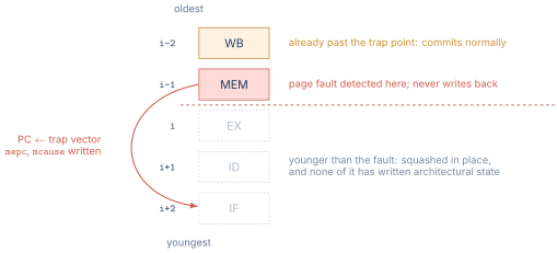
Figure 1 shows one such instant, with the fault in MEM and the squash boundary immediately below it.
In a strictly in-order pipeline, the WB-stage convention costs almost nothing. The instruction in WB had nothing else to do anyway, and adding a fault-check is a single extra wire. The trap-redirect signal then flushes everything in IF, ID, EX, and MEM, and the PC jumps to the handler. The trap-CSRs receive the PC of the WB instruction and the cause code.
The Squash Mechanism
Squashing in this context is the same operation as the branch-misprediction squash from Chapter 30. The control-signal portion of every younger pipeline register is cleared, converting the in-flight instructions into bubbles. The instructions still complete their journey through the remaining stages, but produce no architectural effect.
In some designs, only the relevant control signals are cleared (register-write enable, memory-write enable, branch-update enable, any CSR-write enables). In others, the entire pipeline register is cleared to zeros. Either approach works as long as no younger instruction can update any architectural state after the squash.
The Trap Handler Entry
After the squash, the next-PC mux selects mtvec (or its ISA equivalent) instead of . The IF stage starts fetching from the handler’s entry point. The trap-CSRs (mepc, mcause, mtval on RISC-V) have been written with the trapping PC, the cause code, and any auxiliary data such as the faulting address. The privilege mode is elevated (from user to machine on RISC-V, from EL0 to EL1 on ARM, from ring 3 to ring 0 on x86). Interrupts may be disabled depending on the trap type and the ISA’s convention.
The handler executes, possibly fixes the problem, possibly delivers a signal to the user program, and eventually returns with an MRET (RISC-V), ERET (ARM), or IRETQ (x86-64) instruction. The return restores the saved PC and privilege mode, and execution resumes in the trapped program.
04.Exception Semantics by ISA
The mechanics above are common across ISAs. The conventions differ in three places: how the saved PC is interpreted, how the cause is encoded, and what the handler is expected to do.
RISC-V
RISC-V is the simplest. The privileged specification defines three trap-CSRs at machine level:
-
mepc: the PC of the trapping instruction. After the handler runs,MRETresumes atmepc. -
mcause: a 32-bit (or 64-bit) value whose top bit distinguishes interrupts from exceptions and whose remaining bits encode the cause (e.g., 2 = illegal instruction, 13 = load page fault, 11 = environment call from M-mode). -
mtval: auxiliary data, such as the faulting address for a page fault or the offending instruction word for an illegal-instruction trap.
The trap handler entry point is mtvec. RISC-V supports two trap-handler modes. Direct mode jumps to a single handler that dispatches in software. Vectored mode adds the cause number times 4 to mtvec, jumping to a per-cause stub. The RISC-V approach is intentionally minimal, delegating most policy to the handler software [1].
ARM A64
ARM A64 has a richer model. The privilege levels are EL0 (user), EL1 (kernel), EL2 (hypervisor), and EL3 (secure monitor). Each level has its own trap-CSRs. For a trap taken to EL1, the relevant CSRs are:
-
ELR_EL1: the Exception Link Register, holding the return PC. -
ESR_EL1: the Exception Syndrome Register, encoding the cause in a structured 32-bit format with an exception-class field, an instruction-length bit, and a 25-bit instruction-specific syndrome. -
FAR_EL1: the Fault Address Register, holding the faulting virtual address for memory-abort traps. -
SPSR_EL1: the Saved Program Status Register, holding the processor state (flags, exception level, etc.) at the point of the trap.
The vector base register VBAR_EL1 points to a 2 KiB-aligned vector table with 16 entries of 32 instructions each. The hardware indexes into the table based on the exception type and the source exception level. The table-of-stubs structure is more elaborate than RISC-V’s two-mode scheme [2].
x86-64
x86-64 uses the Interrupt Descriptor Table (IDT), a 256-entry table of descriptors indexed by vector number. The vector number identifies the cause: 0 = divide error, 13 = general protection fault, 14 = page fault, 32-255 = external interrupt vectors. The hardware, on trap, indexes into the IDT, reads the descriptor (which contains the handler’s segment selector and offset), and transfers control to the handler.
The trap also pushes onto the kernel stack: the return RIP, the previous CS, the saved RFLAGS, and for traps that cross privilege levels, the previous RSP and SS. For traps with an error code (such as page fault), an error code is pushed as well. The faulting-address information for page faults comes from CR2, a control register written by the hardware on the trap [3].
Table 1. Trap-CSR conventions across ISAs
| ISA | Saved PC | Cause | Aux |
|---|---|---|---|
| RISC-V | mepc | mcause | mtval |
| ARM A64 | ELR_EL1 | ESR_EL1 | FAR_EL1 |
| x86-64 | stack (RIP) | vector + error code | CR2 |
05.Return from Trap
The reverse direction matters too. After the handler finishes, it executes an ISA-specific return instruction.
RISC-V MRET. Restores the PC from mepc, restores the privilege mode from a field in mstatus, restores the previous interrupt-enable bit, and resumes fetching from mepc.
ARM A64 ERET. Restores the PC from ELR_ELx, restores the processor state from SPSR_ELx, and resumes.
x86-64 IRETQ. Pops the saved RIP, CS, RFLAGS, and, if applicable, RSP and SS off the kernel stack, restoring the user-mode context. SYSRET is a faster alternative used by syscall returns. It makes assumptions about which registers were saved.
In the pipeline, the return instruction is itself a control transfer. It is decoded in ID, evaluated in EX (where the new PC is selected from the relevant CSR), and the squash signal clears any speculatively-fetched user-mode instructions from younger pipeline stages. The PC redirect to the new PC is the same mechanism as a branch redirect.
06.Multiple Faults at Once
In a 5-stage pipeline, several in-flight instructions can be in fault states simultaneously. The instruction in WB has a load page fault. The instruction in EX has a divide-by-zero. The instruction in ID has an illegal opcode. The instruction in IF has an instruction-fetch page fault. Plus an external interrupt just arrived.
The rule is to take the oldest fault. The instruction in WB is the oldest (closest to retirement). Its fault is taken first. Younger instructions are squashed, taking their faults with them. The handler runs. If the handler resolves the WB fault and resumes, the now-restarted instruction (formerly in EX) re-enters the pipeline. If its fault recurs (the divide is still by zero), the trap fires again at WB time. The handler runs again, resolves the EX fault, and so on. Each trap delivers the oldest pending fault, one at a time.
For an external interrupt arriving simultaneously with one or more in-flight exceptions, the convention varies. RISC-V specifies that synchronous exceptions take priority over interrupts. ARM and x86 allow more nuance, with priority levels among interrupt sources.
07.Hardware Additions for Exception Support
The pipeline additions required for full precise-exception support in the 5-stage design are modest:
-
A fault-bit field in each of IF/ID, ID/EX, EX/MEM, MEM/WB (one or two bits, depending on whether cause is also carried).
-
A cause-code field in each pipeline register (typically 4 to 6 bits, sufficient to encode the dozen or so cause types).
-
Fault-detection logic in each stage (instruction decoder, ALU, memory port, fetch-side MMU).
-
A trap-CSR file (
mepc,mcause,mtval,mstatus,mtvec) with read and write paths to the EX stage (forCSRinstructions). -
A trap-redirect path from the WB stage’s fault-check output to the next-PC mux, with the trap-handler address as one of the mux inputs.
-
A squash-all-younger signal driven by the WB-stage trap trigger.
-
A privilege-mode register and its update logic.
The total area cost on a small RV32I implementation is on the order of 200 to 400 flip-flops and a few hundred gates. The performance cost in steady state is zero, because the trap path is exercised only when an exception or interrupt fires.
08.Reorder Buffer Preview
The 5-stage pipeline keeps exceptions precise for free because instructions complete in program order. Modern out-of-order processors complete in any order, which would seem to make precise exceptions impossible. The solution is the reorder buffer, a FIFO that holds every in-flight instruction in program order. Each entry tracks the instruction, its destination register, its computed result (once available), and whether it has experienced a fault.
Instructions enter the ROB in program order at dispatch. They execute in any order, possibly out of program order, and write their results into their ROB entries. They retire in program order from the head of the ROB. At retirement, the result is written to the architectural register file. If the retiring instruction has a fault, the trap is taken at that point, all later ROB entries are flushed, and the pipeline restarts at the handler.
This is the same mechanism as the 5-stage WB-time trap, scaled up. The 5-stage pipeline’s WB stage is, in effect, a one-deep ROB. Out-of-order machines have ROBs holding tens to hundreds of in-flight instructions. The retirement discipline keeps exceptions precise no matter how reordered the execution is.
Chapter 52 develops the ROB in full detail, including retirement, precise exceptions in out-of-order execution, and branch-misprediction recovery. Register renaming is the subject of Chapter 51 and issue queues that of Chapter 53. For this chapter the key point is that the 5-stage pipeline illustrates the underlying principle in the simplest possible form. Once a reader internalizes “trap at the in-order retire point, flush everything younger,” the out-of-order case is a straightforward generalization.
09.Worked Examples
10.Exercises
References
- [1]Waterman, Andrew and Asanovi\'c (2024). “The RISC-V.”
- [2](2024). “ARM.”
- [3](2024). “Intel.”