Execution Units, Ports, and Bypass Networks
September 8, 202642 min readadvanced
Arithmetic Hardware built a Kogge-Stone adder, a Booth-encoded Wallace tree, an SRT divider, and a barrel shifter, each studied alone, with one question asked. How fast does the box compute.
01.Part 1, from arithmetic blocks to a machine
1.1 The execution stage is a switching problem
Arithmetic Hardware built a Kogge-Stone adder, a Booth-encoded Wallace tree, an SRT divider, and a barrel shifter, each studied alone, with one question asked. How fast does the box compute.
A CPU designer faces different questions. How many of each box, which ones share an issue slot, where operands physically come from, and how a result reaches the next instruction fast enough that a dependent chain does not stall. The answer to that last one is the surprise. In a wide out-of-order core the wiring between execution units costs more area, more power, and more cycle time than the execution units. An adder is a few thousand transistors. The network delivering operands to it and carrying its result to the eight places that might want it next is far larger, and it sits on the critical path of every dependent pair in the machine.
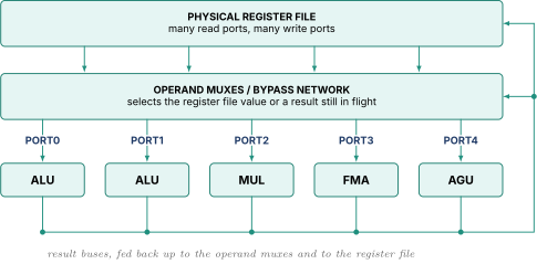
Parts 3, 4, and 5 are about the two middle blocks, not the calculators.
1.2 The three currencies
Every choice below is paid for in area, in power (from in Power Fundamentals and Clock Gating, so long busy wires are the worst case), or in cycle time (from Digital Logic and Timing, where the slowest path anywhere sets the whole chip's frequency). Interesting designs spend one to buy back another. Clustering spends IPC to buy frequency, banking spends occasional stalls to buy area. When asked "would you build X," the expected answer is not yes or no, it is which currency you are spending and what you get.
02.Part 2, latency and throughput
2.1 Two numbers people confuse
Take a multiplier that produces a result 3 cycles after it starts, built as three pipeline stages with flops between them. Ask two questions.
How long until I can use the answer? Three cycles. That is latency.
How often can I start a new one? Every cycle, because the three stages hold three different multiplies. That is throughput, often quoted as its reciprocal the initiation interval, here 1.
Those numbers are independent. Watch three independent multiplies.
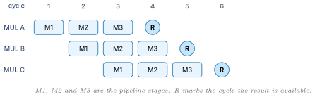
Started on cycles 1, 2, 3. Done on 4, 5, 6. Each waited 3 cycles, and the machine still retired one per cycle. A hundred independent multiplies take about 103 cycles, not 300.
Make them dependent and it collapses.
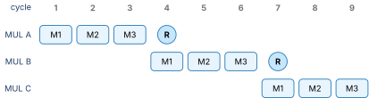
Nine cycles for the same three. Throughput did nothing, because there was never more than one in flight. Latency governs dependent chains, throughput governs independent work. Deciding which regime a loop is in is most of what the top-down analysis in Performance Modeling does.
2.2 The table
Representative figures for a modern high-performance core. Exact numbers vary by design, the shape does not.
| Operation | Latency (cycles) | Throughput | Pipelined |
|---|---|---|---|
| Integer add, sub, logical, compare | 1 | 4 per cycle | yes |
| Integer shift, rotate | 1 | 2 per cycle | yes |
| Integer multiply, 64-bit | 3 to 4 | 1 per cycle | yes |
| Integer divide, 64-bit | 12 to 40, operand dependent | 1 per 8 to 20 cycles | no |
| FP add, FP multiply | 3 to 4 | 2 per cycle | yes |
| FP fused multiply-add | 4 to 5 | 2 per cycle | yes |
| FP divide, square root | 10 to 20 | 1 per 4 to 8 cycles | partially at best |
| SIMD integer add, 128-bit | 2 | 2 to 4 per cycle | yes |
| Load, L1 hit | 3 to 5 | 2 to 3 per cycle | yes |
One row breaks the pattern. Everything pipelines except divide, and "why" is asked constantly. The sloppy answer, that divide is too slow to pipeline, has the causation backwards.
2.3 Why dividers do not pipeline
Divide is slow because it cannot be pipelined cheaply, and the reason is structural, from Arithmetic Hardware.
In a multiplier all partial products are generated at once, because partial product depends only on the multiplicand and bit of the multiplier, both available at time zero. The multiplier is a tree, a feed-forward pile of compressors, and a feed-forward structure can be sliced anywhere by dropping in flops.
In a divider, quotient digit depends on the remainder left by digit . The structure is a loop.
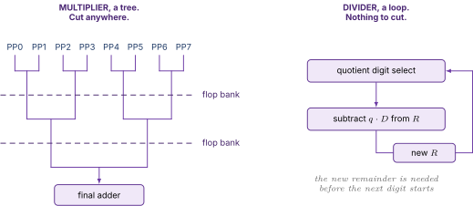
To pipeline the divider you must unroll the loop in space, building 32 physical copies of the digit-select-and-subtract hardware. That works, costs about 32 times the area of one iteration stage, and buys throughput on an instruction that is well under one percent of the dynamic stream. Nobody spends that.
Real designs partially pipeline. Build two or four copies so a second divide can start after 8 cycles rather than 24, or overlap only the feed-forward normalization and rounding around a single-occupancy iterative core. That is why the table says a divider blocks its port for 8 to 20 cycles rather than for its full latency.
Two consequences worth saying out loud. A divide occupies its port and blocks other work, so if integer divide shares port 1 with ALU operations, one divide removes a quarter of your integer issue bandwidth for twenty cycles. And compilers work hard to avoid divide, turning division by a constant into multiplication by a magic reciprocal plus a shift. A real divide in a hot loop means something went wrong upstream.
2.4 Why variable latency breaks speculative wakeup
Notice the divide row says operand dependent. A radix-4 SRT divider retires 2 quotient bits per iteration, so 54 significand bits take 27 iterations while an early-terminating case might take 5. Variable latency sounds like a free win. It is not, and this is the most important idea in this Part.
From Out of Order Execution, the scheduler wakes consumers when a producer's result becomes available. The naive way is to wait until the result exists, then broadcast, then let consumers issue. The fast way is to broadcast before the result exists, timed so operands land exactly when the consumer needs them, which the scheduler can do because it knows the ALU takes exactly 1 cycle.
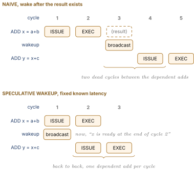
The naive scheme triples the cost of every dependent integer chain, and dependent integer chains are what most code is, so back-to-back issue is not optional in a competitive core. But look at what it requires. The scheduler broadcast the tag before knowing the result existed, purely on the promise that the unit takes exactly 1 cycle. That promise is a hard contract. If the unit ever takes longer, the consumer has already issued, already read garbage off the bypass network, and already computed a wrong answer, and so has everything below it.
A variable-latency unit cannot make that promise. A divider that might take 12 cycles or 27 cannot say in advance which, so it cannot participate in speculative wakeup at all. It signals completion explicitly, the scheduler then broadcasts, and consumers issue the cycle after. The divider eats the two dead cycles of the naive scheme, which against a 20-cycle latency is noise. Correct trade.
The same problem appears somewhere far more important. A load is also variable latency. An L1 hit is 4 cycles, an L2 hit 14, DRAM 200-plus. If loads refused speculative wakeup, everything downstream of every load would pay, and loads feed almost everything. So machines speculate anyway, waking load consumers assuming an L1 hit, and replaying them when the load misses.
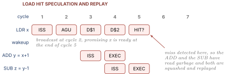
Two design points follow. The replay window is deep, because several dependent levels have issued by the time the miss is known, so a design must choose between precisely tracking the wakeup chain (expensive) and squashing everything in the shadow (over-kill). And replay storms, where replayed work misses and replays again, have been real shipped-silicon performance bugs more than once.
This is why designers hate variable latency in a datapath. Fixed latency is what lets the scheduler run ahead of reality, and running ahead of reality is where much of a wide core's IPC comes from.
03.Part 3, ports
3.1 What a port actually is
An execution port is an issue slot. Physically it is a bundle of wires carrying one decoded operation plus its operand values from the scheduler into the execution region, plus the arbitration logic that picks at most one winner per cycle. Attached to the far end is a set of functional units, and the opcode decides which lights up.
The property people skip is the one that matters. Each cycle the scheduler can send at most one operation down each port. Not one per functional unit. One per port. If port 0 carries an ALU, a shifter, and a multiplier, it can issue an add or a shift or a multiply, never two, even though all three units are idle and capable, because there is one set of operand wires feeding all of them.
Ports, not functional units, are the real constraint on execution width. Twelve functional units on four ports is a four-wide machine.
Why not give every unit its own port? Because each port costs two more register file read ports, one more write port, one more full set of operand mux inputs, one more result bus routed everywhere, and a wider scheduler select tree that must resolve in one cycle. Parts 4 and 5 quantify that. Ports are the most expensive thing you can add to a backend, so designers add few and share hard.
3.2 A concrete port layout
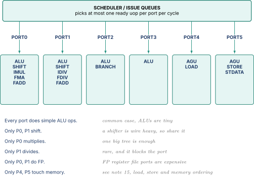
The asymmetry follows from two facts. Instruction mixes are wildly non-uniform, and units differ enormously in cost. Integer add is perhaps a third of dynamic instructions and an ALU is small, so put one everywhere. Multiply is around one percent and a 64-bit Booth-Wallace tree is large, so build one. Divide is a tenth of a percent and the unit is large and port-blocking, so build one and place it where it hurts least. Replicating a divider onto every port would be nearly pure waste, and that sentence is the whole justification for port asymmetry.
3.3 Port pressure, worked with an instruction mix
Asymmetry buys area and costs you when a workload does not match the assumptions. Take a loop body with six uops on the machine above.
| uop | Operation | Ports capable |
|---|---|---|
| 1 | LSL x1, x1, #3 | P0, P1 |
| 2 | LSR x2, x2, #5 | P0, P1 |
| 3 | LSL x3, x3, #1 | P0, P1 |
| 4 | LSR x4, x4, #7 | P0, P1 |
| 5 | MUL x5, x6, x7 | P0 only |
| 6 | ADD x8, x8, #1 | P0, P1, P2, P3 |
Naive count. Six uops, six ports, all independent, so one cycle per iteration.
Count by port instead. Five of the six can only go to P0 or P1, so at least cycles.
| Cycle | P0 | P1 | P2 | P3 | P4 | P5 |
|---|---|---|---|---|---|---|
| 1 | MUL (5) | shift (1) | ADD (6) | idle | idle | idle |
| 2 | shift (2) | shift (3) | idle | idle | idle | idle |
| 3 | shift (4) | idle | idle | idle | idle | idle |
Three cycles per iteration. Eighteen port-slots were available and six were used. Two thirds of the machine's issue bandwidth idled while the loop ran at one third of its apparent width. No amount of reorder buffer or scheduler depth fixes this, because the bottleneck is a structural resource and not a dependence.
Now evaluate a fix. Put shifters on P2 and P3. The crowded group of five now spreads over four ports, cycles, a 1.5x speedup. The cost is two more 64-bit barrel shifters, which per Arithmetic Hardware are six mux layers of almost pure wire, exactly the thing that causes routing congestion in STA Synthesis and Physical Design. So the honest answer to "should we" is that it depends on whether shift-heavy code is a workload you care about, which is a question for Performance Modeling. Structural bound first, cost of relief second, is how to answer this in an interview.
3.4 The general bound
Generalize the arithmetic, because you can apply it on the spot to any mix an interviewer invents. For any subset of uop types, let be how many the loop contains and how many ports can execute any of them.
Check it. All six uops gives . Shifts plus multiply gives . The multiply alone gives . Maximum is 3, matching the schedule. The trick is testing the restrictive subsets, because the tight bound almost always comes from a small group crowded onto few ports. This is what LLVM-MCA automates and what the ports-utilization branch of top-down analysis reports.
3.5 Clustering, which is really about wire delay
Clustering is often mentioned next to port asymmetry, which confuses people. Port asymmetry is about area. Clustering is about wire delay.
Put numbers on the physics. Suppose the execution region is about 1.2 mm across, and a repeated global wire on upper metal propagates at roughly 100 to 150 ps per millimetre once you count repeaters, so sending a 64-bit result from the far left to an operand mux on the far right costs 120 to 180 ps. Now target 4 GHz, so ps. One cross-region hop just ate 120 to 180 ps of a 250 ps budget, before the operand mux, the ALU, and setup time. It does not fit, and per Digital Logic and Timing section 3.2 that one wire has capped the whole core at maybe 2.5 GHz.
Three responses exist and only one is good. Lower the frequency, which penalizes workloads that never cross the region. Make bypass two cycles for everyone, which penalizes physically adjacent dependent pairs. Or cluster.
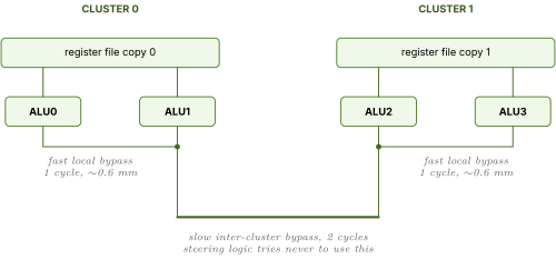
Inside a cluster the wires are 0.6 mm and cost 60 to 90 ps, which fits. Between clusters costs an extra cycle, and dispatch steers dependent instructions into the same cluster so most bypasses stay local.
You give up a few percent of IPC to the inter-cluster penalty and imperfect steering, and get back 15 to 25 percent of frequency because the longest bypass wire halved. For most wide designs that is a clear win. The DEC Alpha 21264, with two integer clusters each holding a replicated copy of the integer register file, is the canonical public example. The bad case is steering failure, where a dependent chain bounces between clusters and every link pays the extra cycle, which is why the steering heuristic ("send it to the cluster that produced its operands") is real microarchitecture and not an afterthought.
04.Part 4, the bypass network
4.1 Why bypass exists
From CPU Foundations Pipeline and Hazards, the naive producer-to-consumer path goes through the register file, and it is too slow. The producer computes in EX and writes back two stages later, so a dependent instruction waits two extra cycles for a value that existed at the ALU output the whole time. Bypass, also called forwarding, is a wire from the ALU output straight back to the ALU input mux. In a five-stage teaching pipeline it is two small muxes and looks like a footnote.
In a wide out-of-order machine it is one of the two or three most expensive structures in the core, and the reason is combinatorial.
4.2 Deriving the cost
Do the count rather than quoting the result, because the derivation is the answer.
Let be the number of ports. Each port's unit produces one result per cycle and consumes two source operands. Ask what a single operand input must select from. It could come from the physical register file, if the producer wrote back long ago, which is 1 source. Or from the result of the unit on port 0, or port 1, and so on, which is more. So one operand input needs a mux with inputs, each 64 bits wide.
How many operand inputs exist? ports times 2 operands, so . Total mux inputs across the network:
and since each input is a 64-bit bus, .
| Ports | Operand inputs | Mux width | Mux inputs | 64-bit wires |
|---|---|---|---|---|
| 2 | 4 | 3 | 12 | 768 |
| 4 | 8 | 5 | 40 | 2,560 |
| 6 | 12 | 7 | 84 | 5,376 |
| 8 | 16 | 9 | 144 | 9,216 |
| 12 | 24 | 13 | 312 | 19,968 |
Going from 4 ports to 8 does not double the bypass network. It multiplies it by 3.6. Four to twelve multiplies it by 7.8 while only tripling the width. That superlinear growth is the most important sentence in this note, and saying it with the derivation is what the question is testing.
Here is drawn out so you can count the taps.
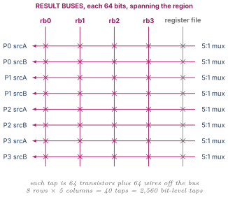
Every X loads its result bus with more capacitance, which per Digital Logic and Timing section 1.2 slows the driver down.
It gets worse, because real machines forward from several pipeline stages, not only the current one. With forwarding levels the mux width becomes and the total is . For and that is mux inputs. A 25-to-1 mux is a tree several levels deep, sitting directly on the dependent-instruction critical path that back-to-back issue in section 2.4 is trying to squeeze into one cycle.
4.3 Why this makes the whole core slower and hotter
Three penalties compound, and naming all three is what makes the answer complete. Cycle time, because the dependent loop is operand mux, ALU, result driver, bypass wire, back into the next operand mux, and that whole loop must close in one period for back-to-back issue to work, so widening deepens the mux and lengthens the wires and frequency drops. Power, because each result bus is 64 bits crossing the region and toggling nearly every cycle, which is close to worst case for and makes bypass a top-three dynamic power consumer in the execution stage. Routability, because thousands of wires must physically route, and congestion in STA Synthesis and Physical Design terms forces detours, detours lengthen wires, and you are back at the first penalty.
Chain it into the sentence an interviewer wants. A wider machine needs a quadratically larger bypass network whose wires are longer and more heavily loaded, which lengthens the dependent-instruction critical path, which lowers frequency, so past some width the IPC gained is worth less than the frequency lost. That is the concrete reason a core cannot simply be made wider, and it beats "diminishing returns" by a mile.
4.4 What designs do about it
Cluster, per 3.5. Two clusters of 4 ports cost taps instead of 144 for one 8-port network, a 44 percent cut, with wires half as long. This is the main mitigation, which is why clustering and bypass are always discussed together.
Prune. Not every port needs a fast path to every other. A 4-cycle multiplier result was never going to feed a consumer one cycle later, so it can go through the register file and the tap can be deleted, at the cost of a more complicated latency table for the scheduler.
Segment the buses with repeaters so a result travels only as far as it needs, saving power on far segments. And reduce operand count, since a three-source FMA needs 50 percent more operand muxes than a two-source add, which is one reason FMA often gets a restricted port set rather than sitting everywhere.
05.Part 5, the physical register file
5.1 Counting the ports
A machine issuing operations per cycle with two sources each must read values and write results per cycle.
For a 6-wide machine that is 12 read ports and 6 write ports. And from Out of Order Execution the physical register file is not small, since it holds one physical register per in-flight result. A machine with a 300-entry reorder buffer might carry 250 physical integer registers of 64 bits, roughly 16,000 bits. Sixteen thousand bits of SRAM with eighteen ports is the problem.
5.2 Why area grows with the square of the port count
A one-read one-write SRAM cell is cross-coupled inverters plus access transistors. Reading asserts a wordline running horizontally and drives a bitline running vertically. Each additional read port needs its own wordline, so it can select the row independently, and its own bitline, so it can deliver the value independently. Same for each write port.
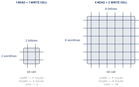
Wordlines run horizontally so their count sets the cell height. Bitlines run vertically so their count sets the width. Both grow linearly with total ports, and area is width times height.
| Configuration | Relative cell area | Versus 1R1W | |
|---|---|---|---|
| 1R 1W | 2 | 4 | 1.0x |
| 2R 1W | 3 | 9 | 2.3x |
| 4R 2W | 6 | 36 | 9.0x |
| 8R 4W | 12 | 144 | 36x |
| 12R 6W | 18 | 324 | 81x |
| 16R 8W | 24 | 576 | 144x |
A 6-wide machine's register file cell is roughly 81 times a simple 1R1W cell. Multiply by 16,000 bits and it becomes one of the largest structures in the core. Area is only the first problem. Delay grows too, because each port hangs another access transistor on the internal node, and power grows because every read discharges a long bitline. The register file in a wide machine ends up simultaneously the largest, slowest, and hottest block in the execution stage, which is why register file read usually gets its own pipeline stage.
5.3 Replication versus clustering
The obvious fix is replication. Two copies, each with half the read ports, both written on every write.
| Organization | Ports per copy | Copies | Total | |
|---|---|---|---|---|
| Monolithic | 12R 6W | 324 | 1 | 324 |
| 2-way replicated | 6R 6W | 144 | 2 | 288 |
| 3-way replicated | 4R 6W | 100 | 3 | 300 |
| 4-way replicated | 3R 6W | 81 | 4 | 324 |
Replication helps, then stops helping, and the table shows why. Splitting read ports shrinks each copy, but every copy still needs all six write ports, because every result must be visible everywhere. The write ports become a floor and past two or three copies you are paying for redundant storage.
Compare clustering, where each cluster keeps only its own results local and gets the others a cycle late.
| Organization | Ports per copy | Copies | Total | |
|---|---|---|---|---|
| Monolithic 6-wide | 12R 6W | 324 | 1 | 324 |
| 2 clusters of 3-wide | 6R 3W | 81 | 2 | 162 |
Clustering halves the register file where replication barely dents it, because clustering cuts the write ports too. That is a second, independent reason clustering wins in wide machines, on top of the wire delay argument in 3.5 and the bypass argument in 4.4. Giving both reasons is a strong answer.
5.4 Banking and the conflict math
Banking splits by address rather than by copy. Divide 256 physical registers into 4 banks of 64, each with a few read ports, and a read goes to whichever bank holds its register. It works because the reads in a cycle usually target different registers. It fails on a bank conflict, when two reads want the same bank and the bank is out of ports, which costs a stall or a replay.
Work a small case you can verify by counting. Four reads per cycle over 2 banks, each bank with 2 read ports, registers uniformly distributed. Each read independently picks a bank, so there are equally likely assignments. Let be the number landing in bank A.
| in bank A | in bank B | Ways | Conflict? |
|---|---|---|---|
| 0 | 4 | 1 | yes, B needs 4 ports |
| 1 | 3 | 4 | yes, B needs 3 ports |
| 2 | 2 | 6 | no, fits |
| 3 | 1 | 4 | yes, A needs 3 ports |
| 4 | 0 | 1 | yes, A needs 4 ports |
Only works, 6 of 16, so the conflict rate is percent.
That is terrible, and it teaches the real lesson. Naive banking, where total bank ports equal total needed reads, conflicts constantly, because randomness clumps. Real banking overprovisions, for example 4 banks of 4 read ports to serve 12 reads. Area is then against a monolithic 324, still a big win, with a conflict rate low enough to ignore.
5.5 Bypass capture
The cheapest register file read is the one you never do. If an operand is arriving on the bypass network this cycle anyway, there is no reason to read the file, and some designs do not even write short-lived values to the file, holding them in bypass latches or a small operand cache and allocating a physical register only if the value survives. The observation behind this is a measured property of programs. Most produced values are consumed exactly once very soon after production, so the giant multiported file is being built for a minority of long-lived values.
The one-sentence summary of Part 5. Register file cost grows with the square of port count, port count grows linearly with issue width, so register file cost grows with the square of issue width, exactly like the bypass network, and together they are why width is the expensive dimension of a core.
06.Part 6, floating point specifics
The format itself is in Floating-Point Arithmetic. What follows is the subset with microarchitectural consequences.
6.1 FMA and why one rounding beats two
FMA computes with a single rounding at the end instead of rounding the product and then the sum. See it in a toy format, decimal with 3 significant digits, round to nearest. Take , , . The exact product is
Separate multiply then add. The multiplier rounds to . The adder computes . The answer is zero.
FMA. The full product is kept at double width inside the unit and the addition happens unrounded. , rounding to .
One says zero, the other says , and FMA is right. The two-step version lost every significant digit, which is catastrophic cancellation, and FMA avoids it because the intermediate was never truncated.
Now the payoff interviewers care about. FMA is cheaper than a separate multiply and add, not more expensive.
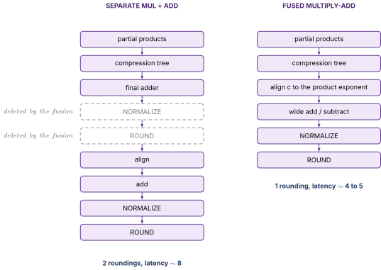
You deleted a whole rounding-and-normalize stage and paid for a wider internal adder and a bigger alignment shifter. That is a good trade, which is why FMA became the primary FP throughput instruction, why plain FADD and FMUL are usually implemented by running the FMA unit with or , and why published peak FLOPS assumes FMA. Two 128-bit FMA units at 4 GHz give a single-precision peak of GFLOPS, where the factor of 2 is "flops per FMA," the accounting convention that makes FMA the headline instruction.
6.2 Denormals, the performance cliff, and the microcode connection
IEEE 754 single precision has 1 sign bit, 8 exponent bits, 23 stored significand bits. For a normal number the exponent field is 1 to 254 and there is an implicit leading 1, so the value is . The smallest normal has exponent field 1 and significand zero, giving
Numbers smaller than that would have to flush to zero, and then would stop implying for nearby small values, which breaks a lot of numerical code. So IEEE 754 defines denormals, also called subnormals. When the exponent field is exactly 0, the implicit leading bit is 0 instead of 1 and the exponent pins at .
Values shrink gradually down to , at the cost of progressively fewer significant bits. Numerically this gradual underflow is a good idea. In hardware it is a disaster.
The fast FP datapath is built on the assumption that every significand has a leading 1 in a known position. The multiplier tree sizing assumes it, the exponent arithmetic assumes it, the normalizer's shift range assumes it. A denormal significand like has an unknown number of leading zeros, so before the fast path can touch it the hardware must detect the case, count leading zeros over 23 or 52 bits, shift left to normalize, carry an internal exponent below the architectural minimum, and on the output side possibly shift right and round in a place the normal rounder was never designed for.
Almost nobody builds that into the fast path, because it would add stages to every FP operation to serve a case that essentially never occurs in well-scaled code. The fast path detects the denormal and bails out to an assist.
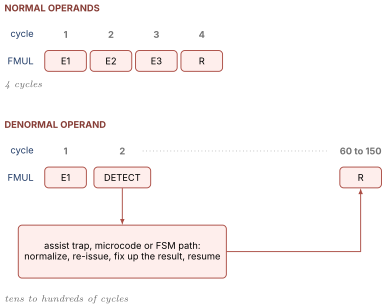
Published penalties for denormal operands or results have ranged from tens of cycles to well over a hundred on shipped designs. A loop that drifts into the denormal range can slow by an order of magnitude with no source change, which is a genuinely mystifying bug from the outside.
The escape hatch is architectural. Flush-to-zero treats denormal results as zero and denormals-are-zero treats denormal inputs as zero, both via the FZ bit of FPCR on AArch64. It makes the cliff vanish and the arithmetic non-conformant, so audio and graphics code enables it happily and scientific code does not.
The microcode connection. The assist can be a hardwired state machine in the FPU, or a trap into microcode that performs the fixup with ordinary instructions and resumes. Microcode is cheaper in area and patchable after tape-out, and slower. Wherever a fast datapath has an architecturally required but rare and awkward case, that pattern recurs, and denormal assists are the textbook example.
6.3 Rounding modes as state that must be ordered
IEEE 754 defines four rounding modes and the default is not what most people guess. Round each value to an integer.
| Value | Nearest, ties to even | Toward zero | Toward | Toward |
|---|---|---|---|---|
| 2.5 | 2 | 2 | 3 | 2 |
| 3.5 | 4 | 3 | 4 | 3 |
| 2.4 | 2 | 2 | 3 | 2 |
In the default mode 2.5 rounds down to 2 and 3.5 rounds up to 4. That is round-half-to-even, and it exists because always rounding halves upward introduces a systematic positive bias that accumulates over long summations. Ties-to-even sends half the ties each way and has no bias.
The mode lives in FPCR on AArch64, along with sticky flags for invalid, divide-by-zero, overflow, underflow, and inexact. Now the microarchitectural problem.
| FADD d0, d1, d2 ; must use the OLD rounding mode | |
| MSR FPCR, x5 ; change rounding mode | |
| FADD d3, d4, d5 ; must use the NEW rounding mode |
In an out-of-order machine the second FADD may be ready long before the first, and the MSR may execute in between. If the rounding mode is a global signal wired to the FPU, the first FADD reads the new mode and produces a subtly wrong answer, with no exception and no crash, just a last-bit difference surfacing as a numerical bug months later.
Two fixes get discussed. Serialize, treating an FPCR write as a barrier that drains the FP pipeline, which is simple and correct and costs tens of cycles, and is what many designs do because mode changes are rare. Or rename it, running FPCR through the rename machinery in Out of Order Execution like any other register, so each FP instruction carries a dependence on the current physical mapping and both FADDs read the right copy. Correct and fast, at the cost of another source operand on every FP instruction and another renamed resource.
The sticky flags have the mirror-image problem, written by nearly every FP instruction rather than read by it, so naively renaming them would serialize all FP through one register. Designs accumulate flags at retirement instead, giving correct architectural values in program order without constraining execution order at all. That is a general trick worth carrying. When state is written often and read rarely, update it at retire rather than at execute.
07.Part 7, SIMD and vectors
7.1 Lanes
SIMD means single instruction, multiple data. One opcode, one trip through decode and rename and schedule, applied to several independent elements packed side by side. AArch64's NEON gives 32 registers of 128 bits, V0 through V31, interpreted by the instruction suffix.
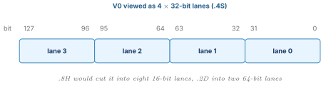
Execute FADD V2.4S, V0.4S, V1.4S with and , and . Four additions, one instruction, four independent narrow adders sitting side by side. The key hardware property is that no information crosses a lane boundary. Lane 1's adder never sees lane 0's carry out, so there are no wires between the lanes at all.
That independence is why SIMD is cheap. Four 32-bit adders cost about what one 128-bit adder costs and are faster, because each carry chain is a quarter as long. You get 4x the arithmetic for roughly scalar area, with no extra fetch, decode, rename, or scheduling. That is the entire economic argument for vectors. The catch is equally simple. The lanes must be doing the same thing to independent data, and code with per-element branches or element-to-element dependences does not vectorize.
7.2 Datapath width versus register width
An implementation choice that is architecturally invisible. The register is 128 bits, the datapath need not be. A 64-bit-wide unit can time multiplex, running a NEON operation in two passes over two cycles, halving area and throughput. The same choice appeared one size up when some x86 implementations executed 512-bit AVX-512 operations on a 256-bit datapath in two passes.
| Register width | Datapath width | Passes | Throughput | Relative area |
|---|---|---|---|---|
| 128 bit | 128 bit | 1 | 1 per cycle | 1.0x |
| 128 bit | 64 bit | 2 | 0.5 per cycle | ~0.55x |
| 256 bit | 128 bit | 2 | 0.5 per cycle | ~1.05x |
A two-pass operation also occupies its port for two cycles, behaving like a small non-pipelined unit, which brings back the port-blocking problem from 2.3.
7.3 Masking and predication
Vectors need a way to say "do this to some lanes and not others," because real loops have if statements. Consider if (a[i] > 0) b[i] = a[i] * 2; over four elements. You cannot branch per lane, so you compute a mask and apply the operation under it. With and , a compare gives and the masked doubling gives .
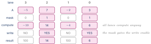
Two details get asked about. First, all lanes compute regardless, because the mask gates the destination write enable and not the arithmetic, so masked code costs full time even when one lane is active. Heavily divergent code therefore wastes most of the machine, which is the same divergence problem GPUs have. Second, NEON builds masks in ordinary vector registers and selects with BSL, while SVE adds 16 dedicated predicate registers P0 to P15 holding one bit per byte-lane, taken as a governing predicate by most instructions. Dedicated predicate registers are real hardware, with their own small file, their own rename resources, and their own dependence tracking, which is a large part of why SVE is a much bigger implementation lift than NEON.
Masking also does safety work. A predicated load does not fault on masked-off lanes, which lets a vectorized loop read past the end of an array safely and removes the scalar cleanup tail.
7.4 Why gather and scatter are hard
An ordinary vector load is easy. LD1 {V0.4S}, [x0] reads 128 contiguous bits, so one address, probably one cache line, one translation, one tag comparison, exactly as cheap as a scalar load of the same size.
Gather takes a vector of indices and loads one element per lane from a different address, as in dst[i] = base[idx[i]]. With the four lanes need four unrelated addresses.
| Resource | Contiguous load | 4-lane gather | 16-lane gather |
|---|---|---|---|
| Effective addresses | 1 | 4 | 16 |
| AGU cycles at 2 per cycle | 1 | 2 | 8 |
| TLB lookups, worst case | 1 | 4 | 16 |
| Cache tag lookups, worst case | 1 | 4 | 16 |
| Distinct lines touched | 1 | up to 4 | up to 16 |
| Pages that could fault | 1 | up to 4 | up to 16 |
| Load queue entries | 1 | up to 4 | up to 16 |
Every column is a structural problem. AGU throughput from Load Store and Memory Ordering caps address generation at two or three per cycle, so a 16-lane gather spends 6 to 8 cycles just producing addresses. The TLB has fixed ports, so translations serialize. The load queue holds only tens of entries, so one gather consumes a large fraction of it.
Then the hard part, precise exceptions. If lane 9 of a 16-lane gather faults and the other 15 succeeded, a naive design re-executes the whole instruction after the fault, redoing 15 loads, and if one of those touched a memory-mapped device with side effects, redoing it is not merely slow but wrong. Designs handle this with per-lane completion tracking, or by cracking the gather into separately retirable micro-operations at decode, or by defining the architecture so the gather updates a mask recording which lanes completed and restarts from there. All three ship in real ISAs.
Scatter is worse in one specific way. Each lane's store goes through the store queue, so a 16-lane scatter needs up to 16 entries in a structure even smaller than the load queue, and it multiplies the store-to-load forwarding search work in Load Store and Memory Ordering, because every younger load must compare against all of them.
State it as. Gather and scatter are hard because one instruction generates many independent memory operations, and every structure in the memory pipeline is sized for one address per instruction.
7.5 SVE and length-agnostic code
NEON hardcodes 128 bits into the encoding, so software assumes 4 single-precision lanes forever and a wider machine needs a new instruction set and recompilation, which is what happened repeatedly on x86 across SSE, AVX, AVX2, and AVX-512.
SVE breaks that. The vector length is implementation defined, any multiple of 128 bits from 128 to 2048, and the encoding does not mention it. Code is vector-length agnostic, using WHILELT to build a predicate covering however many elements remain and INCB to advance by however many bytes the hardware actually holds. The same binary runs correctly on a 128-bit implementation and a 512-bit one, using the full width of each.
The consequences are real. Register file width becomes an implementation parameter rather than an architectural constant. Predicate registers become first-class renamed state. Loop tails disappear, because the predicate naturally covers a partial final iteration. Context switch state size becomes variable, which the OS must handle. For interview purposes, knowing SVE exists, what vector-length agnostic means, and that predicate registers are the mechanism is enough. Vector Microarchitecture and Vector and SIMD Programming Models carry the depth.
08.Part 9, check yourself
Answer out loud, in full sentences, as if an interviewer asked. If you cannot, reread the section named.
- Define latency and throughput for an execution unit and give a case limited by one and completely insensitive to the other. (2.1)
- Why can a multiplier be pipelined but not a divider? Answer structurally, not by saying divide is slow. (2.3)
- What is speculative wakeup, what does it buy, and what promise does it demand of the execution unit? (2.4)
- A divider might finish in 12 cycles or 27. Why is that variability a problem rather than a bonus? (2.4)
- Loads are variable latency too. What does a machine do about that, and what is a replay storm? (2.4)
- What is an execution port, and why is a machine with twelve functional units on four ports a four-wide machine? (3.1)
- A loop has four shifts, one multiply, and one add on the six-port machine in 3.2. Compute the cycles-per-iteration bound and say which subset binds. (3.3, 3.4)
- Derive the bypass network size as a function of issue width. Why does 4 to 8 ports cost 3.6x and not 2x? (4.2)
- State the causal chain from issue width through wire delay to frequency, and use it to explain why cores are not simply made wider. (4.3)
- What problem does clustering solve, what does it cost, and which two structures does it shrink? (3.5, 4.4, 5.3)
- Why does register file area grow with the square of port count? Draw the cell. (5.2)
- Compare replication and clustering for a 6-wide register file with the arithmetic. Why does replication stop helping? (5.3)
- Four reads over two banks with two read ports each. What fraction of cycles conflicts, and what does that say about sizing banks? (5.4)
- Show with small decimal numbers why FMA's single rounding differs from separate multiply and add, and explain why FMA is also cheaper. (6.1)
- Why are denormals slow? Walk through what the hardware must do that the fast path cannot, and say where microcode enters. (6.2)
- A program writes FPCR then immediately does an FP add. What can go wrong out of order, and what are the two fixes? (6.3)
- Why is a masked vector operation no faster than an unmasked one even when one lane is active? (7.3)
- What makes a 16-lane gather hard? Name four structures it stresses and explain the precise-exception problem. (7.4)
09.Part 10, related notes
- Arithmetic Hardware for the adders, Booth multipliers, SRT dividers, and shifters hanging off these ports, and for why divide is iterative
- Out of Order Execution for renaming, the scheduler, and the physical register file whose porting Part 5 costs out
- Load Store and Memory Ordering for the memory ports, AGU throughput, and the store queue that scatter overwhelms
- CPU Foundations Pipeline and Hazards for the simple forwarding case that Part 4 scales until it dominates
- Digital Logic and Timing for the delay model and why the slowest path anywhere sets the whole chip's frequency
- Power Fundamentals and Clock Gating for the switching power equation behind 4.3 and for operand isolation
- STA Synthesis and Physical Design for congestion and why a bypass network is a routing problem as much as a logic one
- SRAM Arrays and ECC for multiported array design, the same porting argument applied to caches
- Performance Modeling for how port pressure surfaces as a core-bound, ports-utilization bottleneck
- Vector Microarchitecture for lane organization, chaining, and vector register file implications beyond Part 7