Case Study: BOOM (Berkeley Out-of-Order Machine)
September 8, 202623 min readadvanced
The preceding chapters of Part V built an abstract out-of-order microarchitecture. Chapter 50 introduced renaming and dynamic scheduling. Chapter 51 factored renaming into a distinct stage with a physical…
The preceding chapters of Part V built an abstract out-of-order microarchitecture. Chapter 50 introduced renaming and dynamic scheduling. Chapter 51 factored renaming into a distinct stage with a physical register file. Chapter 52 added the reorder buffer. Chapter 53 examined the wakeup and select logic. Chapter 54 analyzed memory ordering. another chapter sized the speculative horizon. Chapter 57 pushed the fetch and decode throughput. The previous two chapters added simultaneous multithreading and power management.
The abstract model is useful but ungrounded. Each chapter said "the rename stage allocates from a physical register pool of entries" without committing to a value for . Each chapter said "the issue queue selects ready instructions" without specifying how select is implemented in gates. The textbook treatment is necessary to teach the concepts, but it leaves the question of what the design actually looks like in shipping silicon hanging.
This chapter answers that question by walking through the Berkeley Out-of-Order Machine, an academic open-source RISC-V core whose full RTL is publicly available [1][2]. BOOM is the right case study for two reasons. First, its source is in the open. Every design decision is visible in the Chisel code, with no NDA-protected microarchitecture documentation needed. Second, BOOM is built as a teaching artifact as much as a research vehicle. The design deliberately follows the canonical textbook structure (fetch, decode, rename, dispatch, issue, execute, commit), so it maps directly onto the chapters that came before. The vendor cores in the next chapter (ARM Cortex-X3, Cortex-X4, Neoverse N2) deviate from the textbook form in well-documented ways, and reading BOOM first makes those deviations visible.
The chapter walks BOOM’s pipeline from fetch to commit, identifies each stage’s design choices, and compares the choices against the abstract model from earlier chapters. The full source tree is at github.com/riscv-boom/riscv-boom, with the design notes in docs/. The microarchitecture has gone through three generations: BOOMv1 (2015), BOOMv2 (2017), and BOOMv3, also called SonicBOOM (2020 and later). This chapter focuses on SonicBOOM, the most recently published configuration.
01.Why BOOM as a Case Study
BOOM occupies a unique position in the computer architecture ecosystem. It is the only out-of-order core whose full RTL source is publicly available under a permissive license. Industry cores from Intel, AMD, Apple, and Qualcomm are accessible only through the public manuals and HotChips slide decks, which document externally visible behavior but rarely the internal RTL. Academic cores other than BOOM tend to be smaller or simpler (the original Rocket in-order core, the Ariane / CVA6 RV64GC core, the lowRISC project). BOOM is the only fully out-of-order open RISC-V core at the scale of a modern desktop-class design.
The educational value is substantial. A student who reads the BOOM source after the abstract chapters of Part V can see exactly where each block lives, what bit widths it carries, what control signals flow between stages, and how the design changes between configurations. The Chisel source compiles to readable FIRRTL, then to Verilog, then to a gate-level netlist after synthesis. Each representation reveals different aspects of the same design.
The research value is also substantial. The community has used BOOM as the base platform for studies of speculative side channels (a significant fraction of the published Spectre and follow-on papers use BOOM or a BOOM-derived core), of branch prediction (recent TAGE variants have been evaluated in BOOM first), of prefetcher co-design, and of speculative execution policies. The publishing norms in the field have shifted so that BOOM-based evaluations have become a credible baseline.
02.BOOM’s Pipeline at a Glance
BOOM’s pipeline has ten stages in the default SonicBOOM configuration. Figure 1 sketches the sequence from fetch to commit.
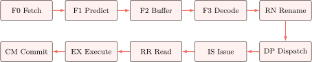
The ten stages map directly onto the abstract pipeline of Part V. F0 through F3 are the front end (fetch, predict, buffer, decode). RN is rename. DP is dispatch to the issue queues. IS is issue select. RR is register read. EX is execute. CM is commit. The LSU pipeline runs in parallel with EX for memory operations.
The pipeline width varies with the BOOM configuration. The four publicly published configurations are SmallBOOM (2-wide), MediumBOOM (3-wide), LargeBOOM (4-wide), and MegaBOOM (5-wide). Each configuration scales the fetch group, the rename width, the dispatch width, the issue queue depths, the reorder buffer depth, and the physical register file size. The table below summarizes the four configurations.
Table 1. BOOM publicly published configurations
| Parameter | Small | Medium | Large | Mega |
|---|---|---|---|---|
| Fetch width | 4 | 4 | 8 | 8 |
| Decode/rename width | 2 | 3 | 4 | 5 |
| Reorder buffer (entries) | 32 | 64 | 96 | 128 |
| Physical regs (int) | 52 | 80 | 112 | 128 |
| Physical regs (FP) | 48 | 64 | 96 | 128 |
| LDQ entries | 8 | 16 | 24 | 32 |
| STQ entries | 8 | 16 | 24 | 32 |
| Branch unit ports | 1 | 1 | 2 | 2 |
| ALU ports | 2 | 3 | 4 | 5 |
| Memory ports | 1 | 1 | 2 | 2 |
| FP/Vector ports | 1 | 1 | 2 | 2 |
Source: BOOM v3 / SonicBOOM published configurations as of the BOOM v3 release notes. The repository at github.com/riscv-boom/riscv-boom carries the src/main/scala/common/parameters.scala file with the authoritative values.
The next sections walk each pipeline group in turn.
03.Front End: Fetch and Predict
BOOM’s front end runs across four stages (F0 through F3). The job is to deliver a steady stream of decoded RISC-V instructions to the rename stage at the configured rename width.
F0: Address generation
F0 generates the next fetch address. The default fetch group is the 32-byte aligned block that contains the current PC, which holds 8 uncompressed RISC-V instructions. If the PC lands partway into that block, only the instructions from the PC to the end of the block are delivered, so an entry at the block midpoint yields 4 instructions rather than 8. The next-PC logic in F0 is straightforward: if the previous cycle had a predicted-taken branch, take the predicted target. If the previous cycle was a sequential fetch, increment by the fetch-group width. If a mispredict has been signaled, take the corrected PC.
The F0 stage also issues the L1 instruction cache lookup. BOOM’s L1 instruction cache is 16 KiB to 32 KiB depending on configuration, 4-way set-associative, with 64-byte lines, so each line supplies two fetch groups.
F1: Branch prediction
F1 runs the branch predictors in parallel with the L1 instruction cache fetch. BOOM uses a TAGE-SC-L predictor as its primary direction predictor, with a return address stack (RAS) and a branch target buffer (BTB) for target prediction. Chapter 56 covered TAGE in depth.
The TAGE configuration in SonicBOOM has 7 tables of history lengths , each with 2048 entries by default. The total storage across the seven tagged tables is roughly 30 KiB. The BTB is to entries depending on configuration. The RAS is entries.
F2: Fetch buffer
F2 buffers the fetched instructions and the predictions made by F1. The buffer holds 16 to 24 entries depending on configuration. The fetch buffer decouples fetch from decode, so that a stall in decode does not immediately stall fetch.
F3: Decode
F3 decodes the buffered instructions, generating the microoperations that flow downstream. RISC-V’s fixed 32-bit encoding (or 16-bit for compressed instructions) makes decode simpler than x86-64’s variable-length decode. BOOM’s decode logic generates one microoperation per RISC-V instruction in most cases, with a small number of multi-uop expansions for compound instructions.
The decoded microoperations are passed to rename one cycle later.
Comparison to the abstract front end
The four-stage front end aligns with the abstract model of Chapter 57, where the PC generator drives the instruction cache and the branch predictor in parallel and the decoder consumes whatever fetch returns. BOOM keeps that fetch-and-predict overlap and adds one stage the abstract sequence does not name, a fetch buffer that decouples fetch from decode.
The fetch width of 8 instructions per cycle in LargeBOOM and MegaBOOM is comparable to commercial server cores. ARM’s Cortex-X3 fetches 6 instructions per cycle. Intel’s Sapphire Rapids fetches up to 8 from the uop cache. The width is a deliberate match for the textbook design, not a compromise.
04.Rename
The rename stage in BOOM maps the architectural register identifiers of the decoded instructions to physical register identifiers.
BOOM uses a unified physical register file approach. The integer physical register pool and the floating-point physical register pool are separate structures (one PRF for integer, one for floating-point), but within each domain the architectural register file is merged into the physical pool. This is the choice covered in Chapter 51 as the merged-file design.
The rename map table holds one entry per architectural register, storing the physical register number that currently holds that architectural register’s value. The free list holds the unallocated physical register numbers. When a new instruction is renamed, its destination architectural register’s mapping is updated to a freshly allocated physical register, and the old mapping is pushed into the reorder buffer so it can be reclaimed at retirement.
The rename width matches the decode width: 2 instructions per cycle in SmallBOOM, scaling to 5 instructions per cycle in MegaBOOM.
Rename map lookup (paraphrased from BOOM)
| // For each of the W renamed instructions per cycle: | |
| for (w <- 0 until renameWidth) { | |
| val srcReg1 = decodedUops(w).rs1 | |
| val srcReg2 = decodedUops(w).rs2 | |
| val dstReg = decodedUops(w).rd | |
| // Lookup the current physical mapping for each source. | |
| val prs1 = renameMap.read(srcReg1) | |
| val prs2 = renameMap.read(srcReg2) | |
| // Allocate a new physical register for the destination. | |
| val newPDst = freeList.allocate() | |
| val oldPDst = renameMap.read(dstReg) | |
| // Update the map and emit the renamed uop. | |
| renameMap.write(dstReg, newPDst) | |
| renamedUops(w) := decodedUops(w) | |
| .withPhys(prs1, prs2, newPDst, oldPDst) | |
| } |
The actual BOOM source is more elaborate because of intra-group dependencies (where one instruction in the rename group depends on a destination produced earlier in the same group) and because of speculative state checkpointing for misprediction recovery. The sketch above shows the principle.
Speculative checkpointing
BOOM allocates a rename map checkpoint on every conditional branch. The checkpoint is the full snapshot of the rename map at the point the branch is renamed. If the branch later turns out to be mispredicted, the recovery logic restores the rename map from the corresponding checkpoint. The checkpoint storage is sized to allow up to 16 in-flight branches by default. If a 17th branch is renamed before the first is resolved, rename stalls.
This checkpoint mechanism is the standard recovery approach for out-of-order pipelines. The alternative is to walk the reorder buffer in reverse from the mispredicted branch, undoing each rename in sequence. The checkpoint approach is faster (one cycle to restore versus tens of cycles to walk) but pays for the checkpoint storage.
05.Dispatch and Issue
After rename, BOOM’s dispatch stage routes each renamed instruction to the appropriate issue queue.
Multiple issue queues
BOOM uses multiple distributed issue queues rather than a single unified queue. The three queues are:
-
The integer issue queue (IQT-INT), serving the ALU pipes and the branch unit.
-
The memory issue queue (IQT-MEM), serving the load and store pipes.
-
The floating-point and vector issue queue (IQT-FP), serving the FP and vector pipes.
The dispatch stage sends each instruction to its matching queue based on the uop’s opcode. The size of each queue varies with configuration: from 8 entries each in SmallBOOM to 32 entries each in MegaBOOM.
The distributed-queue design choice is the same one Chapter 53 discussed under the heading "split versus unified issue queue". The benefit is reduced wakeup-and-select complexity per queue. The cost is that issue bandwidth is fragmented across queues. If integer code dominates and the memory queue sits empty, the empty entries cannot be used by integer instructions. The distributed choice favors a simpler implementation over the maximum utilization of queue capacity.
Wakeup and select
Each issue queue runs its own wakeup-and-select logic. When a producer’s destination physical register is broadcast on the wakeup bus (one bus per execution port), every issue queue entry checks whether either of its source operands matches. If both sources are ready, the entry becomes ready-to-issue.
The select logic picks one or more ready entries per cycle. The select policy in BOOM is age-based: older entries are preferred, implemented through a per-entry age counter that increments each cycle. Age-based select reduces the average waiting time of any particular instruction and avoids the worst case where a single instruction sits at the back of the queue indefinitely.
Replay paths
A load that issues from the memory queue may discover a hazard after dispatch: a previous store with an unresolved address might alias with the load’s address, or the load might miss in the L1 data cache. In either case the load is replayed. The replay path is a side door back into the issue queue, where the load is re-marked as not-ready until the hazard clears.
Replay is part of every modern OoO design and BOOM’s implementation follows the standard pattern documented in Chapter 54.
06.Execute
The execute stage in BOOM houses the ALUs, the branch unit, the load-store units, the multiplier-divider, and the floating-point and vector pipes. The configuration sizes are summarized in the table below.
ALU pipes
BOOM has 2 to 5 ALU pipes depending on configuration. Each pipe executes the basic integer add, subtract, shift, logical, and compare operations in a single cycle. The bypass network connects every ALU output back to every issue queue’s wakeup bus, so that back-to-back dependent integer operations can issue in consecutive cycles.
The bypass network is a key area cost. With 5 ALU pipes broadcasting to 3 issue queues, the comparator complexity grows as the product of producers and consumers. Chapter 53 covered this tradeoff in the abstract. BOOM’s source shows the concrete implementation as parameterized Chisel that elaborates to the specific comparator tree for the chosen configuration.
Branch unit
The branch unit executes conditional and unconditional branches and resolves any mispredictions. A misprediction triggers a front-end redirect and a back-end squash. The branch unit reports the mispredict to F0, which steers fetch to the corrected target, and to the rename stage, which restores the rename map from the checkpoint allocated when the branch was renamed.
The misprediction penalty in BOOM is on the order of 9 to 12 cycles depending on configuration, since the corrected path must refill the four front-end stages plus rename, dispatch, issue, and register read before it reaches execute, which is nine stages.
Load-store units
The LSU has one or two memory pipes depending on configuration. Each pipe accesses the L1 data cache, which is 16 KiB to 32 KiB depending on configuration, 8-way set-associative, with 64-byte lines.
The LSU implements the memory ordering for RVWMO, the RISC-V weak memory order model. RVWMO is weaker than x86-64 TSO and easier to implement, but BOOM still maintains a load-store queue that tracks in-flight memory operations for memory ordering and data-forwarding purposes. Chapter 54 described this in the abstract.
The LSU’s store-to-load forwarding is performed on a byte-mask basis. When a load issues, the LSU checks every older in-flight store whose address is known. If a fully overlapping store is found, the LSU forwards the store data to the load. If a partially overlapping store is found, the LSU stalls the load until the store retires.
Floating-point and vector pipes
BOOM has 1 or 2 FP pipes depending on configuration. Each pipe is a 3-stage pipelined design: the multiply-add fusion is supported, and basic FP add, subtract, multiply, divide, and sqrt are implemented per the IEEE 754 rules covered in Chapter 8.
The vector extension support in BOOM is the RISC-V Vector (RVV) 1.0 specification. The vector unit is a separate datapath from the integer ALUs with its own vector register file. The vector unit size (VLEN) is configurable.
07.Commit
The commit stage retires instructions from the head of the reorder buffer in program order, at up to the configured commit width per cycle. Commit consults the ROB head pointer, the readiness bit of each candidate entry, and the exception status. A ready non-faulting entry is retired: its old physical register mapping is returned to the free list, the corresponding rename map entry is finalized as non-speculative, and any other architectural side effects (PC update, CSR write, store buffer flush) are performed.
A fault or exception detected at commit triggers the exception handler. The fault causes a squash of all younger instructions, a flush of the rename map back to the architectural state, and an exception redirect at fetch. The standard out-of-order recovery mechanism applies, the same as in any merged-file PRF design with checkpoint-based recovery.
The commit width in BOOM matches the rename width. SmallBOOM commits 2 per cycle, MediumBOOM commits 3, LargeBOOM commits 4, MegaBOOM commits 5.
08.Comparison with the Abstract OoO Model
The abstract OoO model from Part V matches BOOM closely. The correspondences are clear in stage names, in structure choices, and in design parameters. The table below puts them side by side.
Table 2. BOOM versus the abstract OoO model of Part� V
| Concept | Abstract model | BOOM choice |
|---|---|---|
| Renaming | Merged PRF | Merged PRF per domain |
| Recovery | Checkpoint | Checkpoint (16 in-flight) |
| ROB | 64-256 entries | 32-128 entries |
| Issue | Split or unified | 3 queues: INT, MEM, FP |
| Select | Age-based or oldest-first | Age-based |
| LSU | Separate load-store queue | Separate LDQ and STQ |
| Forwarding | Byte-mask compare | Byte-mask compare |
| Front end | Fetch-predict-decode | 4 stages: F0-F3 |
| Predictor | TAGE-class | TAGE-SC-L |
Two areas where BOOM differs from the textbook are worth noting.
First, BOOM’s issue queue is split three ways: integer, memory, floating-point. The textbook treatment in Chapter 53 discussed split versus unified queues as a design choice but did not commit to either. BOOM takes the split approach to reduce the wakeup-bus complexity per queue.
Second, BOOM’s front end runs four stages where the textbook model described three, fetch with prediction overlapped and then decode. The extra stage is a fetch-buffer stage that decouples fetch from decode. It exists in practice because the cache access latency rarely fits in a single cycle at the target frequency.
Both deviations are pragmatic optimizations rather than departures from the abstract model.
09.Performance Reported in the Literature
BOOM has been characterized in several academic papers. Reported performance on the SPEC CPU benchmark suite places SonicBOOM in the range of 6 to 7 SPECint per GHz on the LargeBOOM configuration, which is roughly in the same class as a mid-generation ARM Cortex-A78 at the same clock and process. The performance is not at the level of the largest commercial cores (Cortex-X3, Sapphire Rapids, Zen 4) because BOOM has not received the same multi-decade investment in branch prediction tuning, prefetcher co-design, and cache hierarchy parameter tuning that the commercial parts have.
The publicly reported FPGA implementations of BOOM run at 100 to 200 MHz on a high-end FPGA, while ASIC implementations on a TSMC 28nm or 22nm process can reach 1.5 GHz to 2 GHz. The BROOM chip [3] taped out a BOOMv2 instance at 28nm and reported sustained 1.6 GHz with around 4.5 mm of core area including the L1 caches.
The point is that BOOM is fully a real microarchitecture in the class studied in the abstract chapters, not a toy. It is smaller than the largest commercial parts, but it is large enough to make the textbook concepts concrete in shipping RTL.
10.Working with the BOOM Source
The BOOM source tree is organized as a Chisel project under the Rocket Chip generator framework. The relevant directories are:
Table 3. BOOM source tree layout
| Directory | Contents |
|---|---|
src/main/scala/common | Parameters, configurations |
src/main/scala/ifu | Front end (fetch, fetch buffer) |
src/main/scala/exu | Decode, rename, dispatch, execute, commit |
src/main/scala/lsu | Load-store unit |
src/main/scala/bpu | Branch prediction unit |
src/main/scala/v3 | Top-level integration |
docs/ | Design documentation and microarch notes |
A reader who has worked through the preceding chapters of Part V can navigate the source by starting at exu/decode.scala to see decode, exu/rename-stage.scala to see rename, exu/issue-unit.scala to see issue, and so on. Each file maps onto a specific chapter of Part V.
Building and simulating BOOM requires an installed Chisel toolchain (Scala, SBT, FIRRTL, Verilator). The standard simulation flow is documented in the repository README. A small instance (SmallBOOM or MediumBOOM) simulates quickly enough on a modern desktop to be used as a class exercise. A LargeBOOM or MegaBOOM simulation typically requires hours per benchmark run on commodity hardware.
11.Worked Examples
12.Exercises
References
- [1]Celio, Christopher and Patterson, David A. and Asanovi\'c (2015). “The Berkeley Out-of-Order Machine (BOOM.”
- [2]Zhao, Jerry and Korpan, Ben and Gonzalez, Abraham and Asanovi\'c (2020). “SonicBOOM.” In Fourth Workshop on Computer Architecture Research with RISC-V.
- [3]Celio, Christopher and Chiu, Pi-Feng and Asanovi\'c (2019). “BROOM.” IEEE Micro, 39(2), pp. 52--60.