Register Renaming
September 13, 202626 min readadvanced
Tomasulo’s algorithm in Chapter 50 introduced renaming implicitly. The reservation station identifier doubled as the destination tag, so writing the same architectural register from two in-flight instructions…
Tomasulo’s algorithm in Chapter 50 introduced renaming implicitly. The reservation station identifier doubled as the destination tag, so writing the same architectural register from two in-flight instructions yielded two distinct tags. The mechanism worked but tied the rename namespace to the station count, capped the number of in-flight instructions, and tangled the issue logic with the storage logic. Modern out-of-order CPUs separate those concerns through an explicit physical register file backed by a register alias table.
This chapter develops the modern renaming machinery from first principles. A later section reviews the false dependences WAR and WAW and shows that they are entirely artifacts of the architectural register namespace. A later section describes the three core structures (RAT, physical register file, free list) and the cycle-by-cycle mechanics that update them. A later section derives the invariant and uses it to size the physical register file. A later section draws the rename graph for a small program and shows how it reveals the true dataflow. A later section introduces checkpoints and walks through the restore path on a branch misprediction. A later section compares the merged-file design to the older split design.
01.Why Renaming Kills WAR and WAW
The two false dependences from Chapter 30 deserve a closer look in the context of out-of-order execution. Both arise because the architectural register namespace is small (32 integer registers in RISC-V) and gets reused frequently by the compiler. Reuse creates dependences in the register namespace that do not correspond to real dataflow.
Write-After-Read in Detail
The WAR hazard arises in the sequence
I1:
ADD x5, x6, x7(readsx6)
I2:ADD x6, x8, x9(writesx6)
I1 reads x6, I2 writes x6. If I2 reordered ahead of I1, I1’s read of x6 would see I2’s new value instead of the old one the program expects. The hazard is a write-after-read because in the original program order the read precedes the write.
Renaming eliminates WAR because the two uses of x6 become two different physical registers. The rename stage sees that I2 writes x6 and allocates a new physical register, say p17. The RAT entry for x6 is updated from its previous value (say p9) to p17. Before that update, I1 had already read the RAT and captured p9 as its source. I1 now waits for the physical register p9 to hold a value (if p9 is itself produced by an earlier in-flight instruction) or reads it from the file directly. I2 writes its result to p17. The two operations are on different physical registers and have no relationship.
Write-After-Write in Detail
The WAW hazard arises in the sequence
I1:
ADD x5, x6, x7(writesx5)
I2:MUL x5, x8, x9(writesx5)
If I2 completes before I1, the architectural register file would end up holding I1’s value of x5 when the program expected I2’s. A reader of x5 after this pair would see the wrong value.
Renaming eliminates WAW because each write to x5 gets a distinct physical register. I1 writes to one physical (say p21), I2 writes to another (say p35). The RAT for x5 is set to p21 after I1 is renamed, then overwritten to p35 after I2 is renamed. Both writes complete, but only the RAT’s current view of x5, which is p35, propagates to the architectural state on retirement. I1’s value remains in p21, where it is read by any in-flight consumer that captured p21, then p21 returns to the free list when I2, the instruction that displaced it, retires.
02.The Rename Stage Structures
The modern rename stage requires three structures: the register alias table, the physical register file, and the free list. The dispatch logic ties them together in a single pipeline stage that processes one or more instructions per cycle.
The Register Alias Table
The RAT is a small table indexed by architectural register number. Each entry holds the physical register number that currently backs that architectural register. The integer RAT on a modern out-of-order core has 32 entries (one per architectural integer register) of about 8 bits each (to index a 256-entry physical register file).
The table below shows a typical RAT snapshot after a short instruction sequence. The third column records which in-flight instruction last wrote that architectural register.
Table 1. RAT snapshot after a short sequence
| Arch reg | Phys reg | Producing instruction |
|---|---|---|
x0 | p0 | ISA constant zero |
x1 | p41 | I7 |
x2 | p33 | I5 |
x5 | p52 | I9 |
x6 | p17 | I3 |
x10 | p64 | I12 |
Reads to the RAT happen at rename time, one read port per source operand. A 4-wide rename with up to 2 source operands per instruction requires 8 read ports on the RAT. Writes happen at rename time, one write port per destination. The RAT must be checkpointed for branch recovery, discussed in a later section.
The Physical Register File
The physical register file is the storage that holds all in-flight register values. It is significantly larger than the architectural register file. Modern designs allocate between 4 and 12 physical registers per architectural register on the ISAs that expose 32 architectural registers, and a higher ratio on x86-64, whose architectural namespace holds only 16 general-purpose registers. Sizes range from 192 to 384 entries on contemporary cores. The Intel Sunny Cove core, for example, holds 280 integer physical registers backing 16 architectural integer registers, a ratio of 17.5. The Apple M1 Firestorm core is reported to hold around 354 integer physical registers, or about 11 per architectural register.
The physical register file is multi-ported. A 4-wide machine needs 8 read ports (two source operands per instruction times four instructions per cycle) and 4 write ports (one result per instruction times four instructions per cycle). Port count drives area and power exponentially, so designs go to great lengths to reduce the effective port pressure (operand value forwarding, banking, lazy reads).
The Free List
The free list is the queue of physical register numbers that are currently unallocated. At reset, the free list contains every physical register except those backing the initial architectural state. As instructions rename, the rename stage pops one physical register off the free list per destination. As older physical registers become obsolete (their values no longer needed by any in-flight instruction), they return to the free list.
A physical register becomes obsolete when the instruction that overwrote its architectural register has retired. Consider the sequence: I1 writes x5 to physical p21, I2 writes x5 to physical p35. When I1 originally renamed, the RAT entry for x5 was updated from its previous value (say p9) to p21. The previous physical p9 is not yet free, because instructions in flight may still be reading its value through their captured source operand tags.
When I2 renames, the RAT entry for x5 is updated from p21 to p35. The previous physical p21 now joins the "pending free" list. It cannot be freed yet because I1 has not yet retired, and on a misprediction the rollback would need to restore p21 into the RAT.
When I2 retires (which happens in program order, after I1 retires), the pipeline knows that I1 is irreversibly done. The physical register that I1 displaced (which was p9) returns to the free list at I1’s retirement. The physical register that I1 itself allocated (p21) returns to the free list at I2’s retirement.
The free-on-retirement rule guarantees that physical registers stay alive long enough for any consumer to read their value, while still being released as quickly as program-order retirement allows.
The Rename Cycle Mechanics
The cycle-by-cycle behavior of the rename stage, for a single instruction, is the following.
-
Read the RAT to obtain the physical register backing each source operand. The source operands’ physical register numbers become the issue queue entry’s source fields.
-
Pop a physical register off the free list. This physical register will hold the destination’s new value when the instruction completes. The free-list pop is gated by free-list non-emptiness, and an empty free list stalls the rename stage.
-
Write the new physical register number into the RAT entry for the architectural destination. Record the previous RAT value (the physical register that just got displaced) into the reorder buffer entry for this instruction, so that on a rollback the RAT can be restored.
-
Forward the source and destination physical register numbers to the issue queue along with the opcode. The instruction now lives in the issue queue, waiting for its source operands to become value-valid.
Multi-instruction rename (4-wide and beyond) handles intra-cycle dependences with a dependency-checking matrix. If two instructions in the same rename group read a register that a previous instruction in the same group is also writing, the later instruction’s source must be set to the previous instruction’s newly-allocated physical, not to the older RAT value. The matrix is built combinationally from the in-group architectural register comparisons.
03.The P = A + F Bookkeeping
The physical register file’s size determines how many writes the pipeline can have in flight at once. To make this precise, let be the total physical register count, be the architectural register count (32 in RISC-V), and be the count of free physical registers at any moment. Every architectural register is mapped to exactly one physical register through the RAT, accounting for physical registers. The free list accounts for physical registers. The remaining physical registers are in flight, holding values that some in-flight instruction will produce or has produced but cannot yet retire.
Rearranging gives the maximum number of in-flight writes the pipeline can sustain: where is the minimum free-list count that keeps the rename stage from stalling. In practice is zero (the rename can always pop if the free list has at least one entry), but the rename stage stalls when the free list runs dry.
For RISC-V with and , the maximum in-flight write count is . The pipeline can hold 160 writes from in-flight instructions, plus the 32 mappings that constitute the architectural state. Modern designs with reorder buffer depths of 200 to 600 must size accordingly. A 256-entry ROB on RISC-V with implies to avoid free-list stalls under worst-case write density.
Most out-of-order designs target an average free-list occupancy of roughly 10 to 20 percent of , leaving enough slack to absorb instruction bursts without free-list stalls. The slack also covers the latency between an instruction’s retirement and the physical register’s actual return to the free list, which is one to two cycles in typical designs.
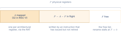
Figure 1 draws that identity as a partition.
04.The Rename Graph
Renaming makes the program’s dataflow explicit. Each in-flight instruction has a unique destination physical register, and each source operand is the physical register number of the producer. The relationships form a directed acyclic graph, called the rename graph, in which nodes are instructions and edges connect producers to consumers.
Consider the sequence
I1:
ADD x1, x2, x3
I2:MUL x4, x1, x5
I3:SUB x6, x1, x4
I4:ADD x1, x7, x8
Before renaming, the architectural namespace shows two writes to x1 (I1, I4) and dependences on x1 from I2 and I3. After renaming, the picture is cleaner. Suppose the initial RAT entry for x1 is p9, and the free list begins with p17, p18, p19, p20.
The table below shows the renamed sequence.
Table 2. Renamed sequence after the rename stage
| Instr | Arch dst | Phys dst | Phys src 1 | Phys src 2 |
|---|---|---|---|---|
| I1 | x1 | p17 | p(x2) | p(x3) |
| I2 | x4 | p18 | p17 | p(x5) |
| I3 | x6 | p19 | p17 | p18 |
| I4 | x1 | p20 | p(x7) | p(x8) |
The rename graph has edges I1 to I2 (through p17), I1 to I3 (through p17), I2 to I3 (through p18). I4 is independent of all three.
The interesting feature is I4. Before renaming, I4’s write to x1 appeared dependent on I1’s write to x1 (a WAW). After renaming, I4 writes to p20 and I1 writes to p17. The two writes are on different physical registers and are entirely independent.
The rename graph reveals two parallel chains.
-
Chain 1: I1 then I2 then I3. Length 3.
-
Chain 2: I4. Length 1.
A 2-wide out-of-order machine can issue I1 and I4 in the same cycle, then I2 and I3 sequentially. The total execution time is 3 cycles (ignoring multi-cycle latency). In the original architectural namespace, the schedule would have looked sequential because of the WAW between I1 and I4.
05.Checkpoints and Misprediction Recovery
Branch prediction sends the pipeline down a speculative path. When the actual branch outcome arrives and disagrees with the prediction, every instruction past the branch must be flushed and the rename state must be rolled back to the point of the misprediction. The rollback requires that the RAT be restored to the state it held immediately before the branch issued.
The standard mechanism is a per-branch RAT checkpoint. When a branch is renamed, the rename stage saves a snapshot of the entire RAT (32 entries on RISC-V, 8 bits each, so 256 bits total) into a checkpoint buffer keyed by the branch’s reorder buffer entry. The checkpoint buffer typically holds 8 to 32 active checkpoints, one per in-flight branch.
On a misprediction, the pipeline does the following.
-
Identify the mispredicted branch’s reorder buffer entry.
-
Flush every instruction in the pipeline newer than that branch. This includes everything in the issue queue, the execution units, and the reorder buffer past the branch’s entry.
-
Restore the RAT from the branch’s checkpoint. The RAT now reflects the state it held immediately before the branch entered rename.
-
Return any physical registers that were allocated to the flushed instructions to the free list.
-
Restore the free list pointer to the value it held when the branch was renamed (the branch itself is not flushed, only what comes after it).
-
Redirect fetch to the correct branch target and resume.
The misprediction penalty is the count of cycles consumed by the flush, the RAT and free-list recovery, and the fetch redirect, plus the latency to refill the pipeline once fetch resumes. Modern designs target 10 to 18 cycles of misprediction penalty depending on how deep the recovery state is in the pipeline.
The alternative to per-branch checkpoints is to roll back the RAT entry by entry using the reorder buffer’s record-of-previous-physical field. The recovery walks the reorder buffer from the misprediction point back to the branch, restoring each architectural register to the previous physical register it held. The walk takes one cycle per ROB entry traversed, which is acceptable only if the misprediction is close to the head of the ROB. For deep speculation, the per-branch snapshot is faster and is the design choice on most modern cores. A hybrid scheme keeps a checkpoint at the most recent low-confidence branch only, walking the ROB for cheaper rollbacks.
06.Merged vs Separate Physical Register Files
Two organizations of physical register storage compete in modern designs. The merged physical register file holds all values (architectural and speculative) in a single array. The separate-file organization keeps the architectural register file as a small distinct array and holds speculative values in a separate rename buffer or in the reorder buffer itself.
Merged Physical Register File
In the merged design, every value the program produces is written to the physical register file. The RAT identifies which physical register currently backs each architectural register. The retirement event simply updates the "retirement RAT" (a second RAT that tracks which physical register holds the most recently retired value of each architectural register). The retirement RAT entry’s previous physical is returned to the free list at the retirement that overwrites it.
The advantage of the merged design is read-port efficiency. A consumer instruction reads its source operand from one physical register file, regardless of whether the value is architectural or speculative. The read port count is the issue width times two operands, with no separate file selection logic.
The disadvantage is write-port count. The single physical register file absorbs every write from every functional unit, requiring as many write ports as there are functional units in the worst case. The port count drives the file’s area and power upward.
The merged design dominates modern out-of-order CPUs. AMD’s Zen 4, Intel’s Golden Cove, Apple’s M-series, and the high-performance ARM Cortex-X cores all use merged physical register files.
Separate Architectural and Rename Files
In the separate-file design, the architectural register file is small (32 entries on RISC-V) and holds only retired values. Speculative writes go to a rename buffer or directly into the reorder buffer’s destination field. At retirement, the result is copied from the rename buffer or reorder buffer into the architectural register file.
The advantage of the separate design is the small, fast architectural file. Reads of source operands that match the architectural state are very fast, and the architectural file’s port count is modest.
The disadvantage is the operand-selection logic. A source operand may be in the architectural file or in the rename buffer. The rename stage records which one it is, and the read stage uses that information to select. The selection adds a multiplexer to the read path, which is on the critical path of the issue-to-execute pipeline.
The separate-file design was common in the 1990s and early 2000s. Intel’s P6 microarchitecture (Pentium Pro through Pentium III) used it. The shift to merged files began with the Intel Sandy Bridge in 2011 and has been industry-wide since.
Table 3. Merged vs separate file comparison
| Property | Merged | Separate |
|---|---|---|
| Storage entries | (large) | + buffer (split) |
| Read ports | On large file | Mux over two files |
| Write ports | On large file | On rename buffer |
| Retirement cost | RAT update | Copy buffer to file |
| Used in | Modern cores | 1990s-2000s cores |