Tomasulo's Algorithm
September 8, 202626 min readadvanced
The in-order limits of Chapter 49 motivated a search for an issue discipline in which an instruction’s position in the pipeline is decoupled from its position in the program. In 1966 Robert Tomasulo, working…
The in-order limits of Chapter 49 motivated a search for an issue discipline in which an instruction’s position in the pipeline is decoupled from its position in the program. In 1966 Robert Tomasulo, working at IBM’s Poughkeepsie laboratory, designed the floating-point unit for the IBM System/360 Model 91 around exactly that principle. His paper, published in 1967, gave the world three ideas that have appeared in every high-performance CPU built since: reservation stations, the common data bus, and implicit register renaming through tags.
The Model 91 had a 60-nanosecond clock and a floating-point unit built around two execution pipelines, an adder and a multiplier that also performed division. Each pipeline was fed by its own set of reservation stations, three on the adder and two on the multiplier, and that is the arrangement the examples in this chapter use throughout. Both pipelines were multi-cycle, and division was much the longest of the three operations. The challenge Tomasulo solved was how to keep those units busy in the face of true dependences and false dependences alike, without freezing the front end when a long-running operation sat at the head of the queue.
This chapter develops Tomasulo’s algorithm from first principles. A later section describes the hardware structures (reservation stations, the register status table, the common data bus). A later section walks through the three pipeline stages (issue, execute, write result). A later section runs a full worked trace of a six-instruction sequence cycle by cycle. A later section explains why Tomasulo’s tag mechanism is implicit register renaming and how it eliminates WAR and WAW hazards. A later section shows how the original algorithm extends to modern designs through a reorder buffer for precise state and a separate physical register file for storage.
01.Hardware Structures
Tomasulo’s algorithm assumes three classes of hardware structure beyond the standard datapath: the reservation stations, the register status table, and the common data bus. Each one solves a specific problem the in-order pipeline could not solve.
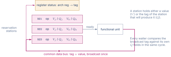
Figure 1 shows how the three fit together.
Reservation Stations
A reservation station is a buffer entry that sits at the input of a functional unit. Each station holds one instruction along with its source operands. The operand fields can be in one of two states. They can hold an actual value (a number), or they can hold a tag (the identifier of some other reservation station that is producing the value). A tag is a small integer that names the producing station, typically the station’s index in its own station array.
The table below lists the fields of a typical adder reservation station. The fields for multiplier and load-store stations follow the same pattern with minor differences (the load-store stations carry an address field, the multiplier stations have wider operand width).
Table 1. Fields of a single reservation station for an adder unit
| Field | Width | Purpose |
|---|---|---|
Busy | 1 bit | Station occupied by an instruction |
Op | 4 bits | Operation code (ADD, SUB, etc.) |
Vj | 64 bits | Value of source operand , if known |
Vk | 64 bits | Value of source operand , if known |
Qj | 5 bits | Tag of station producing , if not known |
Qk | 5 bits | Tag of station producing , if not known |
Dest | 5 bits | Destination register (for renaming bookkeeping) |
A station’s operand is value-valid if its Q field is zero (no producer pending) and tag-valid if its Q field is non-zero (waiting for a producer). When both Qj and Qk are zero, the station is ready and waits only for its functional unit to be free.
Register Status Table
The register status table is indexed by architectural register name. Each entry holds either a tag (the reservation station that will produce the latest write to this register) or a value-valid flag (the architectural register file holds the current value).
When an instruction is issued, the issue stage reads the register status table for each source operand. If the entry has a tag, the issue stage copies that tag into the new station’s Q field. If the entry has value-valid, the issue stage copies the architectural register file’s value into the new station’s V field. When the issuing instruction has a destination, the issue stage overwrites the destination’s status table entry with the new station’s tag, marking that station as the new producer for this architectural register.
This step is the key to renaming. Two instructions that both write the same architectural register get two distinct station tags, and the register status table only points at the younger one. The older write’s result, when it eventually appears on the CDB, will not match the register status table because the table has moved on.
Common Data Bus
The common data bus is a single wire that every functional unit drives when it has a result, and every reservation station and the register file snoop. Each transaction on the CDB carries a tag (which station produced the result) and a value (the result itself).
When a station sees a tag on the CDB that matches one of its Q fields, two things happen atomically. The matching Q field is cleared (set to zero), and the corresponding V field is loaded with the value on the bus. The station now treats that operand as value-valid. If both operands of the station become value-valid in the same cycle, the station is ready to issue to its functional unit on the next cycle.
The CDB is a precious resource. In Tomasulo’s original design there was a single CDB shared across all functional units. Two units finishing in the same cycle would compete for the bus, and one had to defer. Modern implementations provide multiple CDBs, typically one per port of the write ports needed by the issue width.
02.The Three Pipeline Stages
Tomasulo’s algorithm divides the back end of the pipeline into three logical stages. Issue happens in program order. Execute happens in dataflow order. Write result publishes on the CDB and updates every snooping structure. The in-order constraint applies only to issue. Execute and write are free to occur in any order.
Issue
The issue stage takes one instruction at a time off the front of the decoded instruction queue and attempts to place it into a reservation station of the appropriate functional unit. If no station is free for the instruction’s unit, the issue stage stalls (a structural hazard on station capacity).
When a station is free, the issue stage does the following.
-
Look up source operand in the register status table. If the entry has a tag, copy the tag into the new station’s
Qj. If the entry is value-valid, copy the register file value intoVjand setQjto zero. -
Repeat for source operand to fill
VkorQk. -
Write the instruction’s opcode into
Opand setBusyto one. -
If the instruction has a destination register, write the new station’s tag into the register status table at the destination’s entry. This step renames the destination so that any future use of this architectural register will see the new tag.
Issue happens at one instruction per cycle in the original design. Multi-issue extensions allow several issues per cycle subject to station availability and CDB write contention.
Execute
Each cycle the execute stage scans every reservation station looking for stations whose Qj and Qk are both zero (operands value-valid). Among the ready stations, one (or, in modern multi-issue designs, several) is selected and dispatched to its functional unit. The functional unit reads Vj and Vk from the station, computes, and begins the operation’s multi-cycle latency.
Selection among multiple ready stations follows a scheduling policy. The classical choice is oldest-ready, that is, the station holding the instruction earliest in program order among the ready set. Modern designs use age-based or priority schemes, discussed in detail in Chapter 53.
Write Result
When a functional unit completes its operation, it arbitrates for the CDB. Once granted the bus, it drives its result and its producing tag (the station identifier that originated the work) onto the bus for one cycle.
In that cycle, three updates happen in parallel.
-
Every reservation station compares the broadcast tag against its own
QjandQk. Any match clears theQfield and latches the broadcast value into the matchingVfield. -
The register status table compares the broadcast tag against every entry. Any match marks the entry as value-valid and writes the broadcast value into the corresponding architectural register file slot.
-
The producing station itself is freed. Its
Busybit clears, returning the station to the free pool for future issue.
The atomic, broadcast-snoop nature of the CDB is what makes the algorithm work. A single bus transaction simultaneously delivers the value to every consumer that needs it and to the architectural state. No station polls. No software helps.
03.Worked Trace
The most direct way to understand Tomasulo is to trace a small instruction sequence through the algorithm cycle by cycle. The example below follows the classic Hennessy and Patterson presentation, adapted to RISC-V floating-point syntax.
Six-instruction trace sequence
| FLD f6, 32(x2) ; I1: load f6 | |
| FLD f2, 48(x3) ; I2: load f2 | |
| FMUL f0, f2, f4 ; I3: f0 = f2 * f4 (consumes I2) | |
| FSUB f8, f2, f6 ; I4: f8 = f2 - f6 (consumes I2, I1) | |
| FDIV f10, f0, f6 ; I5: f10 = f0 / f6 (consumes I3, I1) | |
| FADD f6, f8, f2 ; I6: f6 = f8 + f2 (consumes I4 and I2, writes f6) |
Assume the latencies are 2 cycles for load (Mem stage), 2 cycles for FADD and FSUB, 10 cycles for FMUL, 40 cycles for FDIV. There are two load stations (Load1, Load2), three add stations (Add1, Add2, Add3), and two multiply stations (Mult1, Mult2). One CDB is shared.
The table below shows the tag structure that each of the six instructions records as it issues (cycles 1 through 6, one issue per cycle). The view deliberately suppresses CDB broadcasts so that every dependence appears as a tag rather than as an already captured value. In the real timeline of the table below the two loads broadcast at cycles 4 and 5, which frees both load stations and replaces every Load1 and Load2 tag in the table with the value that arrived.
Table 2. Reservation station tags recorded as each of the six instructions issues, with CDB broadcasts suppressed
| Station | Busy | Op | Vj | Vk | Qj/Qk |
|---|---|---|---|---|---|
Load1 | 1 | LD | x2+32 | — | — |
Load2 | 1 | LD | x3+48 | — | — |
Mult1 | 1 | MUL | — | f4 | Load2, — |
Add1 | 1 | SUB | — | — | Load2, Load1 |
Mult2 | 1 | DIV | — | — | Mult1, Load1 |
Add2 | 1 | ADD | — | — | Add1, Load2 |
The renaming is visible in the Add2 entry. I6 writes f6, which I1 also writes. When I6 issues, the register status table entry for f6 is updated to point at Add2. From this moment on, any future read of f6 will see Add2’s tag, not Load1’s. Had Load1 still been in flight at that moment, I1’s write to f6 would never have reached the architectural register file, because the register status table entry for f6 would no longer match Load1. In this particular trace Load1 broadcasts at cycle 4, two cycles before I6 issues, so I1’s value does land in architectural f6, and I6’s write at cycle 11 later overwrites it. Either way the renaming guarantees that the final value of f6 is I6’s.
The table below traces the issue, execute, and write-result cycles for each instruction. The columns labeled IS, EX, and WR record the cycle at which each event completes. EX is the cycle the unit begins, EX is when it finishes, and WR is the cycle in which the result appears on the CDB.
Table 3. Cycle-by-cycle timeline of the six-instruction trace
| Instr | IS | EX start | EX end | WR |
|---|---|---|---|---|
| I1 FLD | 1 | 2 | 3 | 4 |
| I2 FLD | 2 | 3 | 4 | 5 |
| I3 FMUL | 3 | 6 | 15 | 16 |
| I4 FSUB | 4 | 6 | 7 | 8 |
| I5 FDIV | 5 | 17 | 56 | 57 |
| I6 FADD | 6 | 9 | 10 | 11 |
The detail worth highlighting is the order of write-result cycles. I1 writes at cycle 4, I2 at cycle 5, I4 at cycle 8, I6 at cycle 11, I3 at cycle 16, I5 at cycle 57. The write-result order is 1, 2, 4, 6, 3, 5. The program order is 1, 2, 3, 4, 5, 6. Three pairs are reordered: I4 before I3, I6 before I3, I6 before I5. Tomasulo’s algorithm allows this reordering because each instruction carries a distinct tag and its value flows to consumers through the CDB rather than through the architectural register file.
Why the Reordering is Safe
The reordering of I4 before I3 is safe because I3 and I4 share no dependence. I3 reads f2 and f4 and writes f0. I4 reads f2 and f6 and writes f8. They share the read of f2 (a structural concern, but Tomasulo serves both reads from their stations’ V fields once the load has broadcast) but no write conflict. They can execute in either order.
The reordering of I6 before I3 is more subtle. I6 writes f6, which is the same register that I1 wrote. If the architectural register file were updated in write-result order, I6’s write at cycle 11 would land in f6, then I3’s write to f0 at cycle 16 would happen, then I5’s write to f10 at cycle 57 would happen. The final architectural state would be I6’s value of f6, which is exactly what the program expects. The issue stage’s renaming arranged it so that I1’s earlier write to f6 is overridden by I6’s later write, regardless of the order in which the two writes actually complete.
04.How Tomasulo Eliminates WAR and WAW
The previous section walked through how Tomasulo’s algorithm permits out-of-order execution. The same mechanism eliminates the false dependences (WAR and WAW) that would otherwise serialize instructions for no semantic reason.
WAR Elimination
Consider the sequence
FADD f1, f2, f3(I1, readsf2)
FMUL f2, f4, f5(I2, writesf2)
I1 reads f2 and I2 writes f2. The WAR hazard would be that I2’s write of f2 arrives at the architectural register file before I1 has finished reading f2. If I2 reordered ahead of I1, the read would see the wrong value.
In Tomasulo, I1’s read of f2 happens at issue time. The issue stage looks up f2 in the register status table. If the entry is value-valid, the value is copied into I1’s reservation station’s V field. If the entry has a tag, the tag is copied into I1’s Q field, and I1 will eventually receive the value over the CDB when that producer completes.
Either way, by the time I2 is issued, I1’s view of f2 is already locked into its reservation station. I2’s later write to f2 cannot affect I1, because I1 is no longer looking at the architectural register file.
WAW Elimination
Consider the sequence
FADD f1, f2, f3(I1, writesf1)
FMUL f1, f4, f5(I2, writesf1)
Both instructions write f1. The WAW hazard would be that I1’s write completes after I2’s write, leaving I1’s value in the register file instead of I2’s. If a third instruction reads f1 after this pair, it would see I1’s stale value instead of I2’s intended new value.
In Tomasulo, I1 issues first and the register status table entry for f1 is set to I1’s tag. Then I2 issues, and the register status table entry for f1 is overwritten with I2’s tag. From the moment I2 issues, the register file’s view of f1 is governed by I2’s producer, not I1’s.
When I1’s result later appears on the CDB carrying I1’s tag, the register status table compares the broadcast tag against its current entry for f1. The current entry holds I2’s tag, not I1’s. The comparison fails, and the register status table refuses the update. I1’s result is still delivered to any reservation station whose Qj or Qk carries I1’s tag (consumers of the older write), but the architectural register file is not corrupted.
The WAW false dependence is eliminated by the simple rule that the register status table holds the tag of the youngest in-flight writer of each architectural register.
05.From Tomasulo to Modern Out-of-Order
The original 1967 algorithm has two limitations that modern designs address. First, it does not preserve precise exceptions. When a multi-cycle instruction takes an exception (a divide by zero, a floating-point overflow), the algorithm cannot in general roll the architectural state back to a clean point in program order, because later instructions may have already updated the register file in out-of-program order. Second, the use of reservation station tags as the renaming namespace is hardware-thrifty but conceptually awkward. The tag space is exactly the size of the station array, which limits the number of in-flight instructions to the total station count.
The two modern fixes are the reorder buffer and the physical register file. Chapter 52 develops the reorder buffer in detail. It is an in-order FIFO that holds every in-flight instruction in program order. Instructions retire from the head of the buffer one at a time, copying their results into the architectural register file only at retirement. The architectural register file therefore advances strictly in program order, even though execution proceeded out-of-order. Exceptions are detected at retirement, at which point all later instructions can be flushed from the pipeline and the architectural state is exactly the state the program expects.
Chapter 51 develops the modern physical register file. The physical register file is much larger than the architectural register file. A typical modern design has 32 architectural integer registers and 192 to 384 physical integer registers. Each architectural register is mapped to one of the physical registers through a register alias table. When an instruction writes an architectural register, the rename stage allocates a new physical register from the free list, maps the architectural register to the new physical, and tells the instruction to write its result to the new physical. The old mapping persists until every consumer of the previous value has completed, at which point the old physical can be freed back to the pool.
These two structures, the reorder buffer and the physical register file, transform Tomasulo’s algorithm from a clever floating-point trick into the spine of every modern high-performance CPU. The reservation station survives in the form of the issue queue. The common data bus survives in the form of the result bus, now multi-ported to keep up with multi-issue. The tag survives as the physical register number. The dataflow discipline survives unchanged.