Case Study: Intel Golden Cove and Redwood Cove
September 13, 202625 min readadvanced
The preceding chapters of Part V developed the modern out-of-order core from first principles. Chapter 50 introduced Tomasulo’s algorithm. Chapter 51 unpacked the physical-register-file rename design. Chapter…
The preceding chapters of Part V developed the modern out-of-order core from first principles. Chapter 50 introduced Tomasulo’s algorithm. Chapter 51 unpacked the physical-register-file rename design. Chapter 52 gave the ROB its commit-in-order contract. Chapter 53 examined the wakeup-select loop. Chapter 54 laid out memory disambiguation. Chapter 55 and Chapter 56 traced branch prediction from bimodal counters to TAGE and perceptron predictors. Chapter 57 examined the instruction-fetch side. Chapter 58 addressed the SIMD backend. Chapter 59 added simultaneous multithreading. Chapter 60 grounded the discussion in dynamic voltage and frequency control.
This chapter, and the AMD chapter that follows, turn from mechanisms to shipping silicon. The subject here is the Intel P-core family from Alder Lake (2021) through Meteor Lake (2023), two generations of the wide-issue out-of-order engine that Intel calls Golden Cove and Redwood Cove. The choice of two consecutive generations is deliberate: it lets the reader see which parameters Intel adjusts between generations and which parameters stay constant for several years.
The chapter relies entirely on public sources. Every claim about a pipeline width, a buffer capacity, a port count, or a latency cycle is supported by Intel’s Optimization Reference Manual [1], a HotChips slide deck, a peer-reviewed paper, or a vendor whitepaper that itself cites those sources. No proprietary microarchitecture details from Intel internals are introduced, in line with the hub’s public-data policy. Where vendor disclosures stop short, the chapter says so and pivots to the academic equivalent rather than guessing.
The reader who has worked through Part V should expect to find familiar mechanisms in every section: the same fetch-decode- rename-dispatch-issue-execute-writeback-commit shape that Chapter 29 introduced for the five-stage in-order pipeline, layered with the speculation and renaming machinery of Chapters Chapter 52 through Chapter 54. The case study makes that machinery concrete on a specific part.
01.Why Golden Cove
Golden Cove is the right Intel P-core to study in depth for three reasons.
First, it is the public anchor for a multi-year product cadence. The same core ships in three families: Alder Lake on the desktop, Sapphire Rapids on the server, and Raptor Lake as the refresh part. That breadth means the public documentation set is unusually complete. The Intel Optimization Reference Manual [1] dedicates several sections to Golden Cove. The HotChips 33 (2021) and HotChips 34 (2022) decks contain frontend, backend, and uncore disclosures. Tom’s Hardware, AnandTech, and ChipsAndCheese ran microbenchmark studies that triangulate the disclosed parameters.
Second, Golden Cove is Intel’s first six-wide-decode P-core. Earlier generations (Skylake, Sunny Cove, Willow Cove) ran four- or five-wide decode. The widening is visible in published numbers and it lets us examine what a wider frontend costs the rest of the pipeline.
Third, Golden Cove is the first Intel P-core to ship in a hybrid configuration alongside Gracemont E-cores. The interactions between the two core types (Thread Director hints, shared L3, the AVX-512 disable on client) illustrate design choices that do not appear in a homogeneous part.
Redwood Cove, the successor, makes a small set of targeted changes. Studying both lets us see what Intel kept and what Intel changed. The deltas are documented in the Meteor Lake HotChips 35 (2023) slides and in the Optimization Reference Manual revision that accompanied the Meteor Lake launch.
02.Pipeline Overview
Figure 1 sketches the Golden Cove pipeline at the level of abstraction this chapter operates in. The exact number of frontend pipeline stages is not publicly disclosed for Golden Cove, but Intel has historically documented the equivalent figure as fourteen to nineteen stages across recent P-core generations. The figure shows the major named structures rather than counting stages.
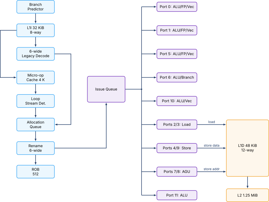
The major named structures and their disclosed sizes are as follows. The L1 instruction cache is 32 KiB, 8-way set associative, with a 64-byte line. The L1 data cache is 48 KiB, 12-way set associative, with a 64-byte line. The L2 cache is 1.25 MiB on client parts and 2 MiB on server (Sapphire Rapids) variants. The ROB is 512 entries. The integer register file is 280 entries and the vector register file is 332 entries. The micro-op cache holds roughly 4000 micro-ops in an eight-way organization, with each way holding up to six micro-ops.
These numbers are uniformly larger than the corresponding numbers in Sunny Cove. The ROB grew from 352 to 512. The integer register file grew from 180 to 280. The micro-op cache grew from 2.25 K entries to 4 K entries. The 32-byte fetch width also doubled from the 16-byte width that Skylake-era P-cores supported when fetching from the L1I. The pattern is the recurring one in microarchitecture press cycles: a wider window, more renamed state, and more issue bandwidth to keep that window fed.
The reader should recognize each block from earlier chapters. Branch prediction is the TAGE-style predictor of Chapter 56. The micro-op cache is the fetch-side optimization of Chapter 57. The allocation queue, rename, and ROB are the renaming machinery of Chapter 51 and Chapter 52. The issue queue and ports are the scheduler of Chapter 53. The load and store ports invoke the load-store queue of Chapter 54.
03.Frontend
The Golden Cove frontend is the path from a fetched instruction byte to a renamed micro-op. It comprises five logical units: the branch predictor, the L1 instruction cache and the associated instruction TLB, the legacy decoders, the micro-op cache, and the loop stream detector. The last three of these are the delivery paths that feed the allocation queue, which is the point at which the in-order frontend hands work to the out-of-order backend.
Branch Prediction
The Golden Cove branch predictor is documented at moderate detail in the Optimization Reference Manual [1] and in HotChips 33 disclosures. It implements a multi-table TAGE-style predictor (Chapter 56) for direction, an indirect-branch target predictor with a substantially larger table than earlier generations, and a return address stack of 32 entries. The branch target buffer is described as "approximately 12,000 entries", a large increase over the 5500 entries documented for Sunny Cove.
The misprediction recovery penalty depends on where the misprediction is caught. If the misprediction is identified in the micro-op cache delivery path, the recovery is shorter than if the misprediction is caught after the legacy decoders. Intel documents the minimum recovery as 17 cycles for Golden Cove, unchanged from Sunny Cove.
The structural take-away is that branch prediction state on a modern P-core consumes meaningful silicon area: tens of kilobits for the TAGE tables, tens of kilobits for the branch target buffer, and additional state for indirect-branch prediction, the return stack, and the conditional-branch direction tables. Chapter 55 introduced the cost in abstract terms. Golden Cove fills in the constants.
Fetch and the L1 Instruction Cache
The L1I is 32 KiB, 8-way set associative, with a 64-byte line. A 32-byte fetch window is delivered to the predecoder each cycle. The L1I miss latency to L2 is publicly documented as 13 to 15 cycles. The instruction TLB is 256 entries for 4 KiB pages and 32 entries for 2 MiB / 1 GiB large pages.
The fetch bandwidth of 32 bytes per cycle is the structural upper bound on how fast instruction bytes can be made available to decode. For an x86-64 stream with an average instruction length of about 4 bytes, 32 bytes per cycle is roughly 8 instructions of fetch bandwidth, more than enough to feed the 6-wide decode that follows. The mismatch is intentional: a wider fetch leaves headroom for branch-taken cycles in which only a portion of the fetch window is useful.
Redwood Cove doubles the L1I capacity on the client variant from 32 KiB to 64 KiB while keeping the 8-way associativity. The change widens the working set the frontend can hold resident without spilling into L2. The server variant retains the 32 KiB capacity. The Optimization Reference Manual revision that accompanied Meteor Lake notes the asymmetry.
Legacy Decode
Golden Cove is Intel’s first six-wide legacy decoder. Earlier generations ran four wide (Skylake, Sunny Cove) or five wide (Willow Cove). The widening is structurally significant. The x86-64 instruction stream is variable-length (one to fifteen bytes per instruction), which makes parallel decode harder than the fixed-width case the RISC-V chapter (Chapter 15) described. Intel’s decoder solves the start-byte identification problem with a predecoder that scans 32 bytes per cycle for instruction boundaries, then dispatches the identified instructions to six parallel decoder slots.
The six slots are not symmetric. One slot is a complex decoder capable of decoding instructions that produce more than four micro-ops. The other five are simple decoders that handle single-micro-op instructions. The complex decoder is the fallback for legacy CISC instructions that translate into microcoded sequences (string operations, FAR jumps, CPUID).
The decoded micro-ops feed both the allocation queue and the micro-op cache. A newly decoded sequence is written into the micro-op cache on the way through, so that a re-fetch of the same code region can be served from the micro-op cache without re-decoding.
Micro-op Cache
The micro-op cache (Intel’s term is Decoded Stream Buffer, DSB) holds approximately 4000 already-decoded micro-ops. The organization is 8 ways per set, with each way holding up to 6 micro-ops drawn from a single 64-byte aligned region of the instruction stream. The delivery bandwidth from the micro-op cache to the allocation queue is documented as 8 micro-ops per cycle, exceeding the 6-wide legacy decode bandwidth.
The structural argument for the micro-op cache is the one Chapter 57 developed in abstract: legacy decode is power-expensive on a variable-length ISA, and re-running it on every loop iteration wastes both power and latency. By caching the decoded form, the frontend skips the predecode-and- decode pipeline when the running code is small enough to fit. The 8-per-cycle delivery rate is the visible bandwidth payoff.
The micro-op cache holds fused micro-ops rather than raw decoder output. Macro-op fusion combines a compare instruction and the immediately following conditional branch into a single fused micro-op that occupies one ROB entry. Micro-op fusion combines two architectural micro-ops (typically an address-generation micro-op and a load or store) into one. Both forms of fusion expand the effective ROB occupancy. A 512-entry ROB holding fused entries can represent significantly more architectural work than 512 unfused micro-ops would.
Redwood Cove widens the micro-op cache delivery path further. The HotChips 35 disclosure notes a higher per-cycle delivery rate, though the exact number is not given in the published slides. Microbenchmark studies after launch placed the delivered bandwidth in the 9-to-10-per-cycle range, suggesting one extra micro-op slot per cycle.
Loop Stream Detector
The Loop Stream Detector is the power-efficient fallback for the shortest loops. When a backward branch closes a loop that fits in the allocation queue, the LSD locks the queue and replays its contents on each iteration without re-fetching from the L1I or the micro-op cache. The L1I, the branch predictor, and the micro-op cache can be clock-gated during LSD operation, which is the principal power benefit.
The LSD capacity on Golden Cove is documented as up to 144 fused micro-ops. The loop must be free of certain micro-op classes (microcoded instructions, certain branch types) for the LSD to engage. The Optimization Reference Manual lists the disqualifying classes in detail.
04.Rename and Dispatch
The Golden Cove rename engine is 6-wide. Per cycle, up to six micro-ops are renamed: their source architectural register identifiers are translated through the register alias table into physical register file (PRF) identifiers, and their destination architectural registers are allocated a fresh PRF entry from the free list. This is the physical-register-file rename design of Chapter 51, scaled to a 6-wide commercial implementation.
The PRF holds 280 integer entries and 332 vector entries on Golden Cove. The vector PRF entries are 512 bits wide, large enough to hold a full AVX-512 vector. On client parts where AVX-512 is disabled in microcode, the upper half of each vector PRF entry is left unused.
The rename stage also handles four idiom optimizations that the frontend can collapse without consuming backend resources. Zero-idiom recognition (xor rax, rax setting rax to zero) does not allocate an integer PRF entry. Move elimination (mov rcx, rdx) does not consume a port and only updates the RAT. Stack engine optimization fuses sequential push/pop into combined operations. NOP elimination drops one-byte and multi-byte NOPs at the rename stage.
The dispatch stage writes the renamed micro-op into the ROB and the issue queues. The unified issue queue is documented as 192 entries on Golden Cove, up from 160 on Sunny Cove. The issue queue is wakeup-select per Chapter 53: each entry holds the rename tags of its source operands and is marked ready when those operands’ wakeup broadcasts arrive.
05.Backend Execution Ports
The Golden Cove backend exposes twelve issue ports, six more than the dispatch width might suggest. The asymmetry is deliberate: many ports are restricted to a single class of operation (loads only, stores only, address generation only), so having more total ports increases the chance that a particular class is not the bottleneck on a given workload.
Table 1. Golden Cove execution ports. Source: Intel Optimization Reference Manual� .
| Port | Functional units | Notes |
|---|---|---|
| Port 0 | ALU, FP, vector, divide | Integer divide unit lives here |
| Port 1 | ALU, FP, vector | 256-bit shuffle and shift |
| Port 2 | Load, AGU | 64 B/cycle load bandwidth with Port 3 |
| Port 3 | Load, AGU | shared with Port 2 |
| Port 4 | Store data | writes value to STD pipeline |
| Port 5 | ALU, FP, vector | 512-bit shuffle on server SKUs |
| Port 6 | ALU, branch | primary branch dispatch |
| Port 7 | Store-AGU | store address generation |
| Port 8 | Store-AGU | shared with Port 7 |
| Port 9 | Store data | second STD path |
| Port 10 | ALU, vector | added in Golden Cove |
| Port 11 | ALU | added in Golden Cove |
The peak integer issue width is therefore six ALU operations per cycle (Ports 0, 1, 5, 6, 10, and 11), although restrictions on which port handles which subclass keep most real instruction mixes below that bound. The peak load bandwidth is two loads per cycle for a total of 64 bytes per cycle on the L1D side. The peak store bandwidth is two store-address generations and two store-data dispatches per cycle.
For floating-point and vector work, Ports 0, 1, and 5 are the FP/vector pipelines. Each pipeline holds a 512-bit-wide adder and multiplier on server SKUs (AVX-512 enabled) and a 256-bit- wide adder and multiplier on client SKUs (AVX-512 disabled). The FP fused multiply-add latency is documented as 4 cycles on the standard path.
Vector and AVX-512
Golden Cove’s vector pipeline is structurally identical to its Skylake-X ancestor in one important respect: a single core can sustain two 512-bit fused multiply-add operations per cycle on Ports 0 and 5 when AVX-512 is enabled. That equals 32 double-precision floating-point operations per cycle (8 double-precision lanes times 2 FMA pipelines times 2 floating-point operations per FMA). On client Alder Lake parts, AVX-512 is fused off via microcode and the pipelines operate on 256-bit operands, halving the peak FLOP rate.
The microcode disable on Alder Lake is necessitated by the hybrid arrangement with Gracemont E-cores, which do not implement AVX-512. If AVX-512 were left enabled on the P-cores, a thread migrated from a P-core to an E-core would encounter an illegal instruction. The decision to disable AVX-512 in microcode rather than to add AVX-512 to Gracemont was made explicit in Intel’s Alder Lake launch materials.
The server SKUs (Sapphire Rapids, Emerald Rapids) have AVX-512 enabled and add the AMX (Advanced Matrix Extensions) tile registers and the TMUL fused matrix-multiply instructions. AMX sits beside the vector pipeline and is described in the Optimization Reference Manual as a separate execution domain. The case study does not unpack AMX in depth, since matrix engines belong with domain-specific accelerators, which lie beyond this book.
06.Memory Pipeline
The Golden Cove memory pipeline comprises the L1D, the L2, the load-store queues, and the prefetcher mix.
The L1D is 48 KiB, 12-way set associative, with a 64-byte line. The capacity grew from 32 KiB on Sunny Cove. The 12-way associativity matches the L1D index structure: 64 sets times 12 ways times 64 bytes per line gives 49152 bytes, which is exactly the 48 KiB headline. The L1D supports two 32-byte (256-bit) loads per cycle, totaling 64 bytes per cycle.
The L2 is 1.25 MiB on client parts and 2 MiB on Sapphire Rapids SKUs. The L2 latency is 15 cycles on the standard hit path. The L2 prefetcher is a stream prefetcher and an IP-stride prefetcher, both of which can independently issue prefetch requests.
The load queue holds 192 entries on Golden Cove, up from 128 on Sunny Cove. The store queue holds 114 entries. The combined load-store queue (LSQ) is the structure of Chapter 54, scaled. The 192-entry load queue permits a substantial number of in-flight loads, large enough that the ROB (512 entries) and the load queue rarely run out of slots in the same cycle.
07.Out-of-Order Window
The window of in-flight micro-ops that Golden Cove can speculatively maintain is bounded by the ROB capacity (512 entries), the issue queue capacity (192 entries), and the load and store queue capacities (192 and 114 entries respectively). The smallest of these is the binding constraint on a given workload mix.
Compute-bound workloads with few memory operations exhaust the ROB first. The 512-entry capacity allows the core to look roughly 512 fused micro-ops past a stalled retirement point. On a typical IPC of 3, that is roughly 170 cycles of look-ahead.
Memory-bound workloads press on the load queue too, though not hard enough to displace the ROB. With 192 load entries and an average load mix of about 25% of all micro-ops, the ROB-equivalent capacity is approximately 192 / 0.25 = 768 micro-ops, larger than the ROB itself. The ROB is the bind in practice.
The actual bind shifts when memory latency dominates. A chain-of-pointer-chase workload with 99% L1D miss rate stalls the load queue much more often than the ROB. The Optimization Reference Manual [1] dedicates several pages to this trade-off in its tuning guide.
08.Differences in Redwood Cove
Redwood Cove is the small-delta successor to Golden Cove. The publicly documented changes are concentrated in the frontend.
The L1 instruction cache doubles in capacity on the client variant from 32 KiB to 64 KiB while keeping the 8-way associativity. The change reflects the larger working sets of modern client workloads (web browsers, Electron applications) that overflow a 32 KiB instruction footprint.
The micro-op cache delivery bandwidth widens from 8 micro-ops per cycle to a number Intel does not publicly specify but microbenchmark studies place between 9 and 10 micro-ops per cycle.
The branch predictor tables grow modestly. The HotChips 35 disclosure notes a larger TAGE structure without giving the exact entry count.
The backend is largely unchanged. The 12 execution ports, the 192-entry issue queue, the 512-entry ROB, the 280-entry integer PRF, and the 332-entry vector PRF carry over from Golden Cove. The L2 capacity on the client variant remains 1.25 MiB. The L1D capacity remains 48 KiB.
The stability of the backend across Golden Cove to Redwood Cove illustrates a pattern: Intel widens and tunes the frontend between generations far more often than it grows the backend. The backend’s binding constraint is power and area at the issue queue and the ROB, both of which scale super-linearly. The frontend’s structures (L1I, micro-op cache, decoders) scale roughly linearly with capacity, so they are easier to grow.
09.Public-Source Triangulation
A practical question for the reader is how to verify the numbers in this chapter. Intel’s Optimization Reference Manual [1] is the primary source, but several parameters are published only in HotChips slides or are inferred from microbenchmarks.
The triangulation strategy works as follows. For each parameter, locate the value in three independent sources. The ROB capacity, for instance, appears in the Optimization Reference Manual, in the HotChips 33 slide deck, and in ChipsAndCheese microbenchmark results. A claim that all three agree on can be cited with confidence.
When sources disagree, the difference is usually a definitional one. The ROB "size" sometimes counts unfused micro-ops and sometimes counts fused micro-ops. The L1D "latency" sometimes includes the AGU pipeline stage and sometimes does not. The reader who tries to reproduce the numbers should be alert to these definitional shifts.
10.Worked Examples
11.Exercises
References
- [1](2024). “Intel.”