Frontend Bandwidth
September 8, 202620 min readadvanced
The backend of a modern out-of-order core can sustain an issue rate of 4 to 8 instructions per cycle if the renamer, issue queues, and execution units are sized correctly. The chapters of Part V so far have…
The backend of a modern out-of-order core can sustain an issue rate of 4 to 8 instructions per cycle if the renamer, issue queues, and execution units are sized correctly. The chapters of Part V so far have built that backend: the reorder buffer in Chapter 52, the renamer in Chapter 51, the issue queues in Chapter 53, and the load-store queue in Chapter 54. Each one is sized to feed an IPC target of 4 to 8.
The frontend has to keep up. If the frontend delivers only 4 instructions per cycle on average, an 8-IPC backend will run at 4 IPC. The backend’s wider machinery is wasted. The frontend is therefore one of the most contested resources on a modern core, and frontend bandwidth has been the principal bottleneck for many workloads since the late 2000s.
This chapter develops the frontend from first principles. It starts with the fetch and decode pipeline, develops the multi- fetch I-cache and the alignment problem on variable-length ISAs, covers the x86 decode bottleneck and the uop cache that mitigates it, treats the loop buffer for short loops, walks through macro-op fusion and micro-op fusion as bandwidth-recovery techniques, and closes with the dense encoding tricks that ARM AArch64 and RISC-V use to keep their fixed-length decoders fed.
01.The Fetch Pipeline
The fetch pipeline starts at the PC generator. Each cycle, the PC generator produces a fetch address and sends it to the instruction cache and the branch predictor. The I-cache returns a block of bytes (typically 32 or 64 bytes), and the branch predictor returns a prediction (next PC) that the fetch engine uses on the following cycle.
A concrete numerical example fixes the picture. Intel’s Sunny Cove fetches 16 bytes per cycle from its 32 KiB L1 instruction cache. The fetch is aligned to a 16-byte boundary, so the 16 bytes returned span a fixed window in the cache line. If the branch target lands in the middle of the window, the bytes before the target are wasted. AMD’s Zen 4 fetches 32 bytes per cycle from a 32 KiB L1 I-cache. ARM’s Neoverse V2 fetches 32 bytes per cycle from its 64 KiB L1 I-cache.
Fetch bandwidth in bytes per cycle, divided by the average instruction length, gives the upper bound on decoded instruction throughput. On a fixed 4-byte ISA like AArch64 with no compression, 32 bytes per cycle is 8 instructions per cycle. On x86-64 with a 4.0-byte average instruction length, 16 bytes is about 4 instructions per cycle. On RISC-V with the C extension enabled, 32 bytes per cycle is 10 to 12 instructions per cycle because the average compressed-mixed instruction length is 2.5 to 3 bytes.
The branch predictor (Chapter 55, Chapter 56) governs how the PC generator advances. On a not-taken branch (or no branch), the next PC is the current PC plus the fetch width. On a taken branch, the next PC is the predicted target. The predictor itself must produce this next PC within one cycle of the fetch, or the fetch stalls. A predictor with multi-cycle latency must therefore overlap with the I-cache access, and modern designs pipeline the predictor in the same way the I-cache is pipelined.
A second-level prediction structure, sometimes called the decoupled fetch or fetch-ahead mechanism, runs ahead of the actual fetch to prefetch I-cache lines that the predictor believes will be needed. This decouples the predictor’s throughput from the I-cache’s latency. The decoupled-fetch FIFO holds future PCs that the predictor has emitted but that the fetch engine has not yet consumed.
02.Decode Bandwidth
After fetch, the bytes go to the decoder. On a fixed-length ISA like AArch64 or RISC-V (without C), the decoder is parallel and simple. Each 4-byte instruction lands in its own decode slot. A 32-byte fetch produces 8 instructions in parallel decode in one cycle.
On a variable-length ISA like x86-64, the decoder is the harder problem. x86 instructions range from 1 byte to 15 bytes. To decode two consecutive instructions in parallel, the decoder must know where the second instruction begins, which requires knowing the length of the first. The length depends on the opcode, the mod-r/m byte, the SIB byte, the displacement, and the immediate, all of which require decoding the first instruction to determine. Serial length-decoding is the natural fit, but it caps decode at one instruction per cycle, which is far too slow.
The standard solution is predecode. The fetch stage tags each byte with a "start of instruction" bit, so the decoder can identify all instruction boundaries in parallel once the predecode bits are available. Predecode happens on I-cache fill: when a new line enters the L1 I-cache, the predecoder walks the bytes once and computes the boundary bits. The boundary bits sit in extra metadata storage alongside the I-cache data. Subsequent fetches read the boundaries in parallel with the data.
Even with predecode, the x86 decoder is complex. The legacy decoder on Intel’s Sunny Cove is a 4-wide complex / simple split. The "complex" decoder slot can decode any x86 instruction and emits 1 to 4 micro-ops. The "simple" decoder slots can decode only single-micro-op instructions. The decode bandwidth is up to 4 instructions per cycle from the legacy decoder, but only when the instruction mix is right.
The decoder output goes to the decoded instruction queue (IDQ), which buffers micro-ops between the decode stage and the renamer. The IDQ smooths out cycle-to-cycle variation. If the decoder emits 4 micro-ops one cycle and 0 the next, the renamer reads from the IDQ at its constant rate (6 micro-ops per cycle on Sunny Cove) and never sees the variation.
The IDQ also serves as the multiplexing point between the legacy decoder and the uop cache. When the uop cache hits, the renamer reads from the uop cache instead of the decoder. The IDQ allows either source to feed the renamer at its full rate, and the selection happens per cycle based on which source has valid micro-ops available.
03.The Micro-Op Cache
The x86 legacy decoder is expensive in area and power. It is also the slowest part of the frontend on hot code. The micro-op cache (uop cache) caches the decoder’s output, so that frequently-executed code paths can bypass the decoder on subsequent passes.
Intel’s Decoded Stream Buffer (DSB) holds 2.25 K uops on Sunny Cove, organized as 48 sets of 8 ways with up to 6 uops per way entry. AMD’s Op Cache on Zen 3 holds 4 K uops with similar organization. At the 3.5 to 4.0 byte average x86 instruction length quoted later in this chapter, those capacities amount to roughly 8 to 16 KiB of decoded x86 code, which covers most inner loops.
On a fetch, the frontend checks the uop cache and the legacy decoder path in parallel. If the uop cache hits, the frontend delivers uops directly to the IDQ at the uop cache’s higher throughput (6 uops per cycle on Sunny Cove and 8 uops per cycle on Golden Cove, versus 4 uops per cycle from the legacy decoder). If the uop cache misses, the legacy decoder takes over.
The uop cache hit rate on typical workloads is 70 to 90 percent, depending on the working set and the regularity of the code. Hot inner loops sit in the uop cache. Cold or sparse code spills to the legacy decoder. The combination delivers higher sustained decode bandwidth than the legacy decoder alone could provide.
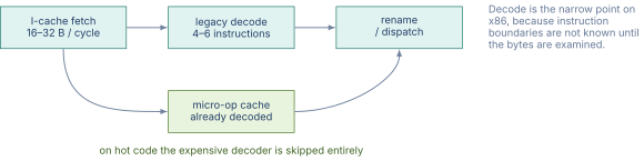
Figure 1 shows where the width is lost and regained.
The Trace Cache
A more ambitious version of the uop cache was the trace cache, introduced by Rotenberg, Bennett, and Smith in 1996 [1]. The trace cache stores sequences of uops that span branch boundaries, indexed by the starting PC and the predicted directions of the branches in the sequence. A trace cache hit delivers a multi-block sequence of uops in one fetch, bypassing both the I-cache and the branch predictor for the cached trace.
The trace cache shipped in Intel’s Pentium 4 (NetBurst). It was dropped in Core and Nehalem, which shipped no decoded-uop cache at all, and eventually replaced by the simpler uop cache that first appeared in Sandy Bridge, because the trace cache’s complexity in construction and replacement did not pay off as well as a straightforward block-cached uop cache. The uop cache caches single blocks. The trace cache caches sequences across blocks. Modern designs settled on the simpler approach.
04.Loop Buffers
A still smaller cache for the still-hotter case is the loop buffer, also called the loop stream detector (LSD) on Intel designs. The LSD holds the most recently issued sequence of uops in a small queue at the top of the IDQ. When the frontend detects a backward branch that has been taken several times to the same target, it locks the LSD: subsequent iterations of the loop replay from the LSD without re-fetching from the I-cache or even the uop cache.
The LSD on Sunny Cove is 64 entries. A 64-uop loop body fits entirely in the LSD. Loops smaller than 64 uops run from the LSD at the renamer’s full rate, with both the I-cache and the uop cache idled. Both power and bandwidth benefit, the power because the rest of the frontend can clock-gate, the bandwidth because the LSD has no alignment or capacity miss issues.
The LSD has constraints. The loop body must not contain calls, returns, or far jumps. It must fit in the LSD’s entry count. The LSD is invalidated on any frontend redirect. In practice, tight inner loops like the body of a memcpy or a SAXPY satisfy these constraints and run from the LSD. Larger loops or those with nested function calls run from the uop cache or the legacy decoder.
05.Macro-Op Fusion
Some sequences of two x86 instructions perform what is logically one operation. The most common is a cmp followed by a jcc, which computes a comparison and branches on the result. The compare itself produces no register that the following branch needs, except through the flags register, which is hidden in the architectural state.
Macro-op fusion recognizes this pattern at decode and emits a single internal micro-op that performs both operations. The fused uop occupies one entry in the ROB, one entry in the issue queue, and one issue slot. The backend sees what was two x86 instructions as one micro-op, which recovers issue bandwidth.
Intel and AMD both implement macro-op fusion for several patterns:
Table 1. Common x86 macro-op fusion patterns
| Pattern | Description |
|---|---|
cmp + jcc | Compare and branch |
test + jcc | Test and branch |
add + jcc | Add and branch (flag-setting) |
sub + jcc | Subtract and branch |
and + jcc | AND and branch |
inc + jcc | Increment and branch |
dec + jcc | Decrement and branch |
Source: Intel SDM Vol. 3 and AMD APM Vol. 3. Exact rules vary by microarchitecture generation.
A typical inner loop has a compare-and-branch at the bottom (the loop exit test). Without fusion the loop has uops where is the number of body uops. With fusion the loop has uops because the compare-and-branch combines into one. On a tight loop, this is a 10 to 20 percent reduction in uop count, which maps directly to a 10 to 20 percent IPC improvement if the backend was the bottleneck.
AArch64 and RISC-V do not need macro-op fusion in the same way because their conditional branches do not depend on a separate flag-setting instruction. RISC-V’s beq, bne, blt, etc., perform the comparison and branch in a single instruction. AArch64’s compare-and-branch instructions (cbnz, cbz, tbz, tbnz) cover many common cases natively. The fixed-instruction ISAs absorb at the instruction set level what x86 has to recover at the microarchitecture level.
06.Micro-Op Fusion
Micro-op fusion is a different optimization that operates on the uops a single instruction decodes into. An x86 mov [mem], reg is two uops: the store address computation and the store data write. Without fusion, both uops occupy separate entries in the issue queue. With fusion, they occupy one fused entry, and the issue queue schedules them as a unit.
The micro-op fusion benefit is the issue queue and reorder buffer entry count savings. A program that issues 100 store uops would occupy 200 issue queue entries (and 200 ROB entries) without fusion. With fusion it occupies 100 of each. The backend structures, which are sized in entries rather than in instructions, hold more work.
The cost is added complexity in the issue queue, which must track the fused pair and issue the two halves through separate execution ports when the time comes. Intel has implemented micro-op fusion since the Core architecture, and AMD has done so since Zen 1. The patterns include the store-address-and-data pair and the load-and-arithmetic pair (the latter on instructions like add reg, [mem] which loads from memory and adds to a register in one instruction).
07.Dense Encodings: RISC-V C and ARM Compressed
RISC-V and ARM both ship optional dense-encoding extensions that shrink common instructions from 4 bytes to 2 bytes.
RISC-V’s C extension (compressed) provides 16-bit encodings for the most frequent instructions: c.add, c.mv, c.li, c.lw, c.sw, and others. Each 16-bit compressed instruction is defined to be functionally equivalent to a 32-bit base instruction with restricted operands (e.g., only the eight registers x8 through x15, only small immediates). The decoder expands the compressed instruction to its 32-bit form before the rest of the pipeline sees it, so the rest of the pipeline can treat all instructions as 32-bit.
The bandwidth benefit is roughly 25 to 30 percent fewer code bytes for typical code. With the C extension enabled, a 32-byte fetch can carry up to 16 instructions (all compressed) instead of 8. The effective fetch IPC bound increases by 1.25 to 1.5 times on dense code.
AArch64 does not ship a compressed encoding in the base ISA, but the related ARM Thumb-2 instruction set (used on ARM Cortex-M embedded cores, not on AArch64 server cores) achieves similar density. AArch64 instead achieves dense code through its rich instruction set: compare-and-branch, conditional-select, load-pair, and store-pair instructions encode in one 4-byte instruction what would take two on a simpler ISA. The effective density is similar without the variable-length cost of compression.
x86-64’s variable-length encoding gives it the densest code of the three by some measures, but at the cost of the legacy decoder complexity discussed above. The average x86 instruction length on typical workloads is 3.5 to 4.0 bytes. RISC-V with C is 2.5 to 3.0 bytes. AArch64 is 4.0 bytes (no compression). The bandwidth- weighted decode complexity varies the other way.
Table 2. Frontend characteristics across ISAs
| ISA | Avg instr length | Decode cost | Fetch IPC (32B) |
|---|---|---|---|
| x86-64 | 3.5–4.0 bytes | high | 8–9 |
| AArch64 | 4.0 bytes | low | 8 |
| RISC-V | 4.0 bytes | low | 8 |
| RISC-V +C | 2.5–3.0 bytes | medium | 10–12 |
Source: synthesized from vendor documentation and SPEC binary analyses. Numbers approximate.
08.The Frontend as Bottleneck
A wide out-of-order backend can sustain 6 to 8 IPC if the frontend feeds it. The frontend rarely does on real workloads. Typical SPEC integer code, server transactions, and JIT-compiled bytecodes deliver 3 to 5 sustained IPC on a backend that could in principle do 8.
The reasons are layered. I-cache misses cost 10 to 30 cycles each. BTB misses cost 1 to 3 cycles. Branch mispredictions cost 15 to 25 cycles. Uop cache misses cost the difference between uop-cache and legacy-decoder throughput. Frontend bubble cycles from any of these compound across the pipeline and starve the backend.
The performance counter community has converged on the "top-down" analysis (Yasin, 2014) that classifies each cycle into "frontend bound," "backend bound," "bad speculation," and "retiring." On typical workloads, 25 to 40 percent of cycles are frontend-bound. This is comparable to the backend-bound fraction and confirms that the frontend is at least as important as the backend on performance-sensitive code.
09.Worked Examples
10.Exercises
References
- [1]Rotenberg, Eric and Bennett, Steve and Smith, James E. (1996). “Trace Cache: A Low Latency Approach to High Bandwidth Instruction Fetching.” In Proceedings of the 29th Annual International Symposium on Microarchitecture (MICRO), pp. 24--34. doi:10.1109/MICRO.1996.566447