Issue Queues and Schedulers
September 8, 202623 min readadvanced
The out-of-order pipeline of the previous three chapters has been described as if instructions automatically issue when their operands are ready. That description hides the hardest structure in the whole…
The out-of-order pipeline of the previous three chapters has been described as if instructions automatically issue when their operands are ready. That description hides the hardest structure in the whole machine. The issue queue holds dozens to hundreds of in-flight instructions, each waiting on between zero and two sources. Every cycle, the queue must determine which entries have become ready, choose a subset to issue, and broadcast each issued instruction’s destination tag so that dependent instructions on the next cycle can become ready.
The wakeup-select loop in this paragraph is the central problem of high-performance out-of-order design. It dictates clock frequency in many designs, dictates power in most, and dictates verification complexity in all. A later section reviews the scheduler’s task and positions it relative to renaming and retirement. A later section develops the wakeup logic as a content-addressable memory. A later section develops the selection logic. A later section shows why wakeup and select together form the critical path. A later section compares distributed and unified queue designs. A later section compares data-capture and non-data-capture schedulers. A later section discusses scheduling priority policies. A later section covers how IQ designs scale beyond 60 entries.
01.The Scheduler’s Role
The scheduler sits between renaming and execution. At rename time, an instruction is allocated an issue queue entry. The entry holds the instruction’s opcode, its destination physical register, its source physical register numbers, and one ready bit per source. The entry’s ready bits are initialized at rename time from the result-bus snoop of prior in-flight values (some sources may already have produced results, in which case the bit is set immediately) or by checking the physical register file’s ready flags.
Each cycle, the scheduler performs two actions, wakeup followed by select within the same cycle.
-
Wakeup: every IQ entry compares each broadcast tag on the result buses against its own source tags. Each match sets the corresponding ready bit.
-
Select: the scheduler examines all entries whose ready bits are all set. It picks a subset of size up to the issue width, respecting functional-unit availability, and dispatches them.
The wakeup and select actions are intertwined. An entry that wakes up this cycle becomes eligible for selection this cycle (in a back-to-back issue design) or next cycle (in a non-back-to-back design). Back-to-back issue is critical because a chain of dependent single-cycle instructions (a common pattern in tight loops) must issue one per cycle to keep the pipeline full. If wakeup and select were on separate cycles, dependent instructions would issue one every two cycles, halving the IPC on dependent code.
The IQ is sized to balance five pressures. Larger IQ buys more in-flight instructions and more scheduling freedom. Smaller IQ saves wakeup-CAM area, reduces select latency, and lowers power. Modern designs range from 60 total entries on power-efficient cores to more than 350 on high-performance ones, with the trend toward distributed queues to keep per-queue size manageable.
02.Wakeup as a CAM
Each IQ entry holds, for each source operand, a physical register tag and a ready bit. When a result-bus broadcast arrives, the broadcast tag is compared against every entry’s source tag in parallel. Matches set the matching ready bit.
The structure is identical to a CAM. The CAM cell stores the source tag and compares it against the broadcast tag in one gate delay. The match signal feeds an SR latch that becomes the ready bit. Figure 1 shows the structure.
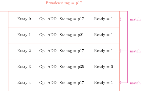
The CAM size scales as the IQ entry count times the source operand count times the result bus count. For a 60-entry IQ with 2 source operands per entry and 4 result buses, the CAM has comparators. Each comparator is an 8-bit equality check. The fan-in to each ready-bit latch is the number of result buses (4 in this example) since any of them can broadcast a matching tag.
The wakeup CAM is one of the IQ’s two dominant power sinks. The CAM is activated every cycle by every result-bus broadcast, and the activity factor approaches one. Modern designs reduce wakeup power by gating the CAM activation on result-bus activity (skip the wakeup cycle if the result bus is idle) and by using lower-power CAM cell designs.
03.Selection
Selection takes the set of ready entries (those with all source ready bits set) and chooses up to the issue width of them to dispatch this cycle. The selection must respect functional-unit availability: an ALU operation cannot be sent to the divider, a load cannot be sent to the ALU, and the load-store unit has limited ports. The selection must also follow a priority policy that determines which entries get picked first when more are ready than can issue.
The Selection Tree
The standard selection structure is a binary tree of arbiters. Each tree leaf represents one IQ entry. Each internal node arbitrates between its two children and forwards one ready signal up the tree. The root produces the index of the chosen entry. A second tree with the same structure but a different priority order (typically older versus younger) produces a second choice, and so on up to the issue width.
For a 60-entry IQ with 4-wide issue, four parallel selection trees run. Each tree’s depth is levels of arbiter logic. The selection latency is therefore roughly 6 gate delays, often the longest combinational path in the back end.
Priority Policies
The arbiter at each level chooses between its two children according to a policy. The simplest policy is fixed priority (always prefer the left child if both are ready). Fixed priority biases selection toward one end of the IQ and creates starvation risk for entries at the other end.
Age-based priority, the dominant choice on modern designs, gives priority to the older of two ready entries. Age is tracked either by allocation timestamp (a wraparound counter) or by physical position in the IQ if the IQ is implemented as a collapsing buffer (entries shift down as older entries issue, so position correlates with age).
Critical-instruction-first is a third option, in which the scheduler heuristically estimates which ready instruction is on the longest remaining dependence chain and gives it priority. The estimation logic is non-trivial and the performance gain over age-based priority is small on most SPEC workloads, so this policy is rarely deployed in commercial designs.
Table 1. Selection policies and their typical use sites
| Policy | Performance | Used in |
|---|---|---|
| Fixed-priority | Lowest | Pedagogical only |
| Round-robin | Low | Embedded cores |
| Age-based | High | Modern desktop/server cores |
| Critical-first | Marginal gain | Research designs |
The performance ranking is empirical. SPEC integer benchmarks see age-based selection deliver 5 to 10 percent higher IPC than round-robin, and critical-first improves on age-based by 0 to 3 percent. The marginal benefit of critical-first does not justify its hardware cost on general-purpose cores.
04.The Wakeup-Select Critical Path
The critical path of the out-of-order back end is the wakeup-select loop. For back-to-back issue of dependent single-cycle instructions, the following must happen in one clock cycle.
-
A previous cycle’s instruction completes execution and broadcasts its result tag.
-
The wakeup CAM compares the broadcast tag against every IQ entry’s source tags. Matching entries set their ready bits.
-
The selection logic identifies the new set of all-ready entries and produces up to the issue width of selected entries.
-
The selected entries’ source values are read from the physical register file (in a non-data-capture design) or directly from the IQ entry (in a data-capture design).
-
The selected entries are dispatched to their functional units, which begin computing.
All five steps must fit in one clock period for back-to-back issue. The wakeup CAM and the selection tree each take several gate delays. The PRF read in non-data-capture designs takes one of the cycle’s heaviest budgets. The dispatch routing to the functional unit adds final delay. Together they pin the clock period from below.
The equation above captures the constraint.
The numbers on a 2024-era 5 GHz design come out roughly as ps, ps, ps, ps, totaling 200 ps, which is the full 5 GHz clock period. The wakeup-select loop is the limiter of single-cycle back-to-back issue.
Two design techniques alleviate the wakeup-select pressure without sacrificing back-to-back issue. Speculative wakeup optimistically wakes up the consumer one cycle before the producer’s result is on the bus, on the assumption that single-cycle latency operations always finish on time. This compresses wakeup into the producer’s execute cycle rather than the post-execute cycle, gaining one cycle on the loop. The cost is recovery logic for the rare case when the producer takes longer than the latency the wakeup assumed (a load’s consumers are woken on the assumption that the access hits in the L1 at the expected load-use latency, and a miss forces re-execution of the speculatively-woken consumers).
A second technique is loose scheduling, in which wakeup happens reliably on the cycle after the broadcast and the scheduler accepts that back-to-back single-cycle dependent issue is one cycle slower. This is suitable for designs where the dependent-chain frequency is moderate and the clock-frequency headroom from the relaxed wakeup is more valuable than the few percent IPC loss.
05.Distributed vs Unified Issue Queues
A unified issue queue holds all in-flight instructions in a single buffer. A distributed organization places separate queues in front of each functional unit. The choice has consequences for scheduling flexibility, CAM size, and dispatch routing.
Unified Queue
The unified IQ is a single CAM serving all functional units. Every entry can in principle be sent to any unit of compatible type. The selection logic must choose among all ready entries.
The unified design’s advantage is scheduling flexibility. Two ADD operations that arrive in the same cycle can be sent to either ALU. The scheduler does not have to commit at rename time to one ALU or the other.
The unified design’s disadvantage is CAM size. A 96-entry unified queue with 2 source operands per entry and 8 result buses requires a CAM with 96 entries times 2 sources times 8 buses, totaling 1536 comparators in the worst case. Power is similar.
Intel’s P6 through Skylake used unified queues. The IQ sizes grew from 20 entries on Pentium Pro to 97 entries on Skylake. Beyond Skylake, Intel moved to a distributed design.
Distributed Queue
The distributed IQ has separate queues for each functional unit class. ALU queues, multiplier queues, divider queues, load queues, store queues. Each queue is smaller and serves fewer broadcast buses.
The distributed design’s advantage is per-queue size. A 20-entry ALU queue plus a 16-entry load queue plus a 16-entry store queue plus an 8-entry multiplier queue totals 60 entries with much smaller per-queue CAMs.
The distributed design’s disadvantage is dispatch commitment. At rename time, each instruction is assigned to a specific queue based on its operation type. If the chosen queue’s capacity is exhausted while others have room, rename stalls even though the total in-flight capacity is available. The mismatch between workload mix and queue distribution causes inefficiency.
AMD’s Zen 4, Intel’s Golden Cove and successors, ARM’s Cortex-X3, and Apple’s M-series all use distributed queues. The per-queue sizes are tuned to typical workload mix, with 20 to 30 entries per ALU queue being common.
Table 2. Issue queue organization in modern cores
| Core | Organization | Total IQ entries |
|---|---|---|
| Intel Skylake | Unified | 97 |
| Intel Sunny Cove | Mixed | 160 |
| Intel Golden Cove | Distributed | 160+ |
| AMD Zen 3 | Distributed | 120 |
| AMD Zen 4 | Distributed | 144 |
| Apple Firestorm | Distributed | 354 |
| ARM Cortex-X3 | Distributed | 192 |
06.Data-Capture vs Non-Data-Capture
A data-capture scheduler stores the actual source values in the IQ entry along with the ready bits. When all sources are ready, the entry already has the values needed to send to the functional unit. Operands that are already available when the entry is allocated are read from the PRF at allocation time, and operands produced later are captured straight off the result bus, since every IQ entry whose source matches the broadcast tag latches both the ready bit and the value.
A non-data-capture scheduler stores only the source tags and ready bits. When an entry is selected for issue, the functional unit reads the source values from the PRF using the source tags. The IQ does not hold values.
Data-Capture Tradeoffs
Data-capture eliminates the PRF read from the wakeup-select critical path, shortening the cycle. The PRF read happens in parallel with execution rather than serially. This buys the wakeup-select loop one stage of slack, allowing higher clock frequency.
The cost is wider IQ entries. Each entry now holds two 64-bit values (or two 128-bit values for vector operations), bringing entry width from roughly 30 bits to 160 bits or more. The IQ storage area grows by more than a factor of five.
Non-Data-Capture Tradeoffs
Non-data-capture keeps IQ entries small. Each entry needs only the tags and the ready bits. The PRF, however, must have enough read ports to serve every selected instruction’s source reads in one cycle. A 4-wide issue needs 8 PRF read ports (two sources per instruction). The PRF area and power scale with the port count.
Which is Used Where?
Modern designs are split. Apple’s M-series uses data-capture in some queues and non-data-capture in others, balancing per-queue cost against PRF port count. AMD and Intel high-performance cores tend toward non-data-capture with heavily ported PRFs. Embedded and power-efficient cores tend toward data-capture to minimize PRF port count.
07.Age-Based vs Prefer-Oldest Selection
When the selector finds more ready entries than the issue width, it must pick a subset. The typical heuristic is to prefer older entries, on the grounds that older instructions are more likely to be on the critical path of the program’s dataflow graph.
Strict Age-Based
Strict age-based selection assigns each IQ entry a sequence number at allocation. The selector orders entries by sequence number and picks the lowest (oldest) ready ones up to the issue width. The implementation uses a sorted-array structure or a position-based encoding in which the IQ entry’s physical index encodes its age.
Strict age-based gives the strongest critical-path priority. It buys 5 to 10 percent IPC over round-robin on SPEC integer.
Prefer-Oldest with Saturating Age
A simpler variant uses a saturating age counter per entry. The counter increments each cycle the entry waits in the queue. The selector uses the counter as priority. This avoids the sorted-array hardware while still approximating age-based behavior.
Modern Practice
Most modern designs use a position-based encoding in which the IQ is a collapsing buffer. When an entry issues, the remaining entries shift down (or the head pointer wraps forward in a circular layout). The lowest-index entry is always the oldest, and the selector’s preference for low indices implements age-based priority naturally. The collapse logic adds a small amount of per-entry combinational delay.
08.Scaling Beyond 60 Entries
Issue queues above 60 entries face superlinear scaling in delay and power even though their component counts grow only linearly. The wakeup CAM’s comparator count scales linearly with IQ entries, but the broadcast wires that drive every comparator get longer and more heavily loaded as the queue grows, so wakeup delay rises faster than the comparator count does. The selection tree depth grows as , which is slow growth, but the fan-in at each level grows. The collapse-network complexity grows linearly with IQ entries and linearly with the issue width, so it tracks the product of the two.
Modern designs above 60 entries use partitioned issue queues. Each partition is independent and scales like a 60-entry queue. The partitions are typically aligned with the distributed-IQ split: one partition per functional unit class. The Apple M1 Firestorm’s 354-entry scheduler, for example, is split across ALU, branch, load, store, and floating-point partitions, none of which comes close to the 354-entry total on its own.
A second technique is the speculative-wakeup design from a later section. By taking wakeup off the critical path during single-cycle issue, the design escapes the worst of the timing pressure and can accommodate larger IQs without missing the cycle.
A third technique is multi-cycle scheduling, in which the wakeup-select loop spans two cycles rather than one. The penalty is one cycle of dependent-issue latency. The benefit is much larger IQs (200 entries or more) and correspondingly higher in-flight capacity. Some embedded out-of-order cores use this technique, accepting the IPC loss in exchange for larger window and lower frequency target.